Machine tool
A technology for machine tools and robots, applied in metal processing machinery parts, turning equipment, maintenance and safety accessories, etc., can solve problems such as cost increase, robot size increase, actuator size increase, etc., to suppress mechanical stop and improve automation. horizontal effect
- Summary
- Abstract
- Description
- Claims
- Application Information
AI Technical Summary
Problems solved by technology
Method used
Image

Examples
Example
[0034] First embodiment
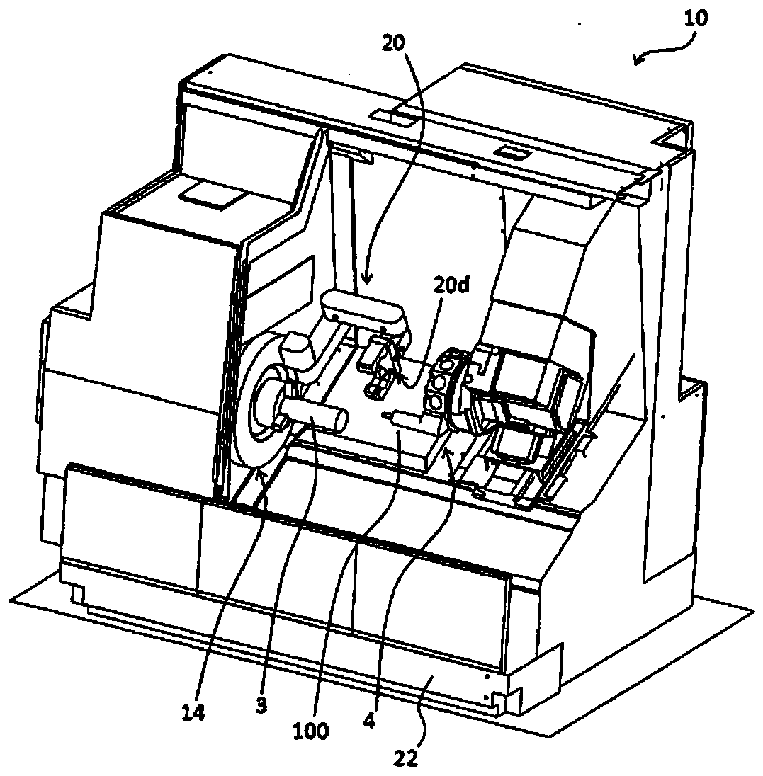
[0035] figure 1 The schematic structure of the machine tool 10 is shown. In the following description, the direction of the rotation axis of the spindle device 14 is referred to as the Z axis, the moving direction of the tool holder 4 orthogonal to the Z axis is referred to as the X axis, and the direction orthogonal to the Z axis and the X axis is referred to as Is the Y axis.
[0036] The machine tool 10 is a machine configured to cut a workpiece with a tool. More specifically, the machine tool 10 has a turning function of cutting the workpiece 3 with an applied turning tool while rotating the workpiece 3, and a rotary cutting function of cutting the workpiece 3 with a rotating tool.
[0037] The outer periphery of the machine tool 10 is covered with a cover (not shown). The space separated by the cover is the machining chamber in which the workpiece 3 is machined. By providing the cover, it is possible to prevent chips and the like from flying outside.
Example
[0053] Second embodiment
[0054] Figure 4 Another state of the cutting tool installed by the in-machine robot 20 is shown.
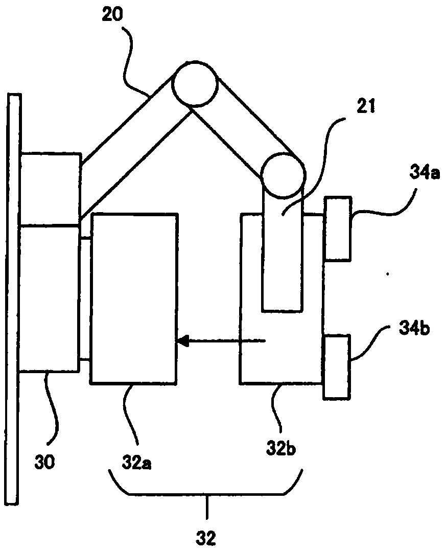
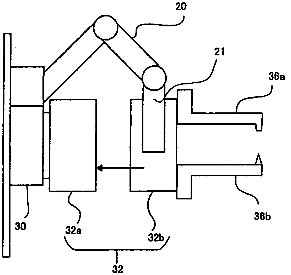
[0055] versus Figure 3A with 3B Similarly, in a state where the second sub-chuck 32b is attached to the first sub-chuck 32a, the hand 21 of the in-machine robot 20 clamps the second sub-chuck 32b formed with a pair of cutting tools 38a and 38b, and It is not the second sub-chuck 32b formed with the claws 34a and 34b. The cutting tools 38 a and 38 b function as a pair of stoppers and blades, and extend in a direction horizontal to the rotation axis direction (Z direction) of the main shaft 30. Similar to the claws 34a and 34b, the pair of cutting tools 38a and 38b includes a pair of main jaws fixed by bolts. The main jaw includes a rack and pinion that can be meshed with the driving mechanism of the first sub-chuck 32a.
[0056] The hand 21 of the in-flight robot 20 clamps the second sub-chuck 32b and moves the second sub-chuck 32b to contact the first sub-ch
Example
[0057] The third embodiment
[0058] in Figure 3A , Figure 3B with Figure 4 Among them, a pair of cutting tools 36 a and 36 b or a pair of cutting tools 38 a and 38 b are arranged to be in contact with each other to cut (shear) chips 38 on the rotation center axis of the main shaft 30. Or like Figure 5 As shown, a pair of curved cutting tools 40a and 40b may be configured to cut (shear) the chips 38 at positions offset from the rotation center axis of the main shaft 30 by a predetermined distance in the X-axis direction.
PUM
 Abstract
Description
Claims
Application Information
 - R&D Engineer
- R&D Manager
- IP Professional
- Industry Leading Data Capabilities
- Powerful AI technology
- Patent DNA Extraction
Browse by: Latest US Patents, China's latest patents, Technical Efficacy Thesaurus, Application Domain, Technology Topic.
© 2024 PatSnap. All rights reserved.Legal|Privacy policy|Modern Slavery Act Transparency Statement|Sitemap