Exhaust manifold

An exhaust manifold, exclusive technology, applied in the field of casting materials, can solve the problem of not achieving the maximum temperature difference, and achieve the effect of avoiding thermal bridge effect

Pending Publication Date: 2019-07-02
乔治费歇尔金属成型科技股份公司
View PDF7 Cites 0 Cited by
  • Summary
  • Abstract
  • Description
  • Claims
  • Application Information

AI Technical Summary

Problems solved by technology

[0004] The disadvantage in this case is that the thermoelectric module is not directly exposed to the effect of the maximum temperature prevailing in the exhaust manifold, but is separated from the internal combustion engine due to the heat shiel

Method used


Image

  • Exhaust manifold
  • Exhaust manifold
  • Exhaust manifold

Examples


Embodiment Construction

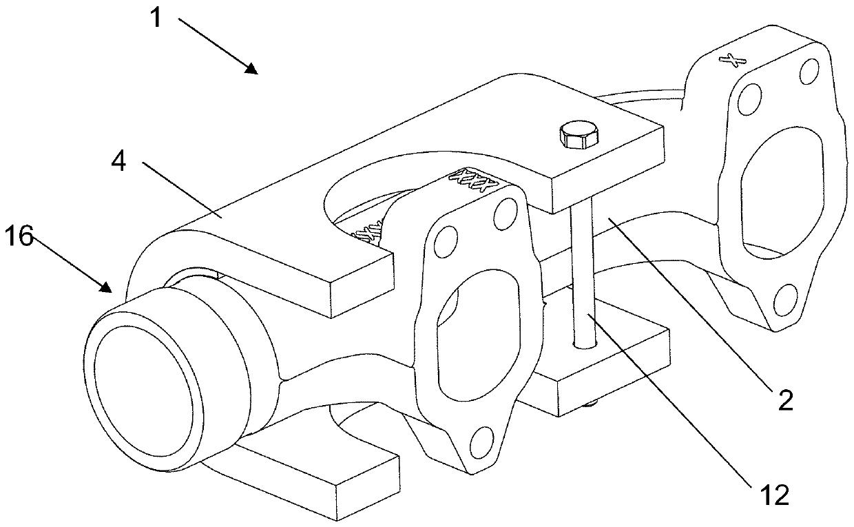
[0026] figure 1 The figure depicted in shows a three-dimensional view of an exhaust manifold 1 according to the invention with thermoelectric elements.

[0027] The illustrated embodiment shows variants in which the thermoelectric elements and cooling elements are attached on both sides, that is to say at the bottom and at the top of the exhaust manifold, but it is naturally also possible Possible embodiments of the exhaust manifold according to the invention are envisaged only at the bottom or only at the top, and only on the front side or on all sides (that is to say at the top, at the bottom and on the front side) have these elements.

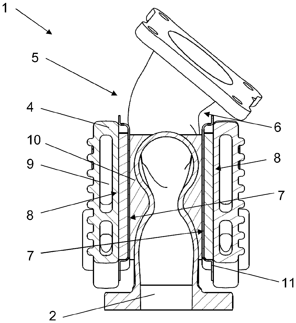
[0028] exist figure 1 In the depicted embodiment, the cooling elements 4 are fastened on the exhaust manifold 2 by means of fastening means 12, wherein, in the depicted embodiment, each is arranged as one on the exhaust manifold The cooling elements 4 on the side 5 and one on the lower side 6 of the exhaust manifold are clamped together. Na


PUM


Abstract

The present invention relates to an exhaust manifold having a thermoelectric element for utilizing waste heat of an internal combustion engine. The exhaust manifold includes an exhaust manifold, preferably comprising a cast material; and at least one thermoelectric element, wherein the thermoelectric element is preferably designed as a plate and generates a voltage as a result of a temperature difference occurring between one side and the opposite side, wherein the at least one thermoelectric element is arranged on the at least one exhaust manifold side, wherein a cooling element is arranged on the thermoelectric element on the side facing away from the exhaust manifold, wherein the cooling element has at least one cooling channel, wherein the cooling channel is used for the through-flow of a fluid.

Description


Claims


Application Information

Patent Timeline
Owner 乔治费歇尔金属成型科技股份公司
Why Eureka
Try Eureka