Cooling conduit

Active Publication Date: 2017-11-21
RENAULT SA
View PDF6 Cites 0 Cited by
  • Summary
  • Abstract
  • Description
  • Claims
  • Application Information

AI Technical Summary

Benefits of technology

[0014]The present invention furthermore has the main advantage that the additio

Problems solved by technology

In the present context of consensus about climate change, the reduction in carbon dioxide (CO2) emissions is a major challenge facing motor vehicle manufacturers, as standards are becoming ever more stringent in this field.
However, this Li-ion technology cannot be used to create traction batteries for EVs without numerous diffi

Method used


Image

  • Cooling conduit
  • Cooling conduit
  • Cooling conduit

Examples


Embodiment Construction

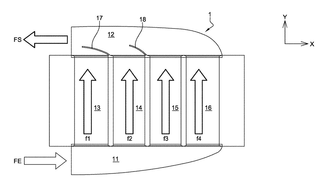
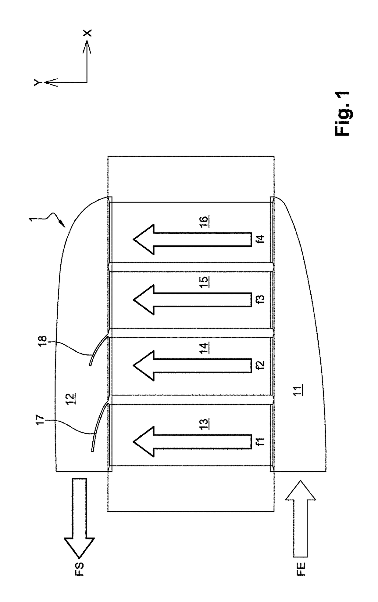
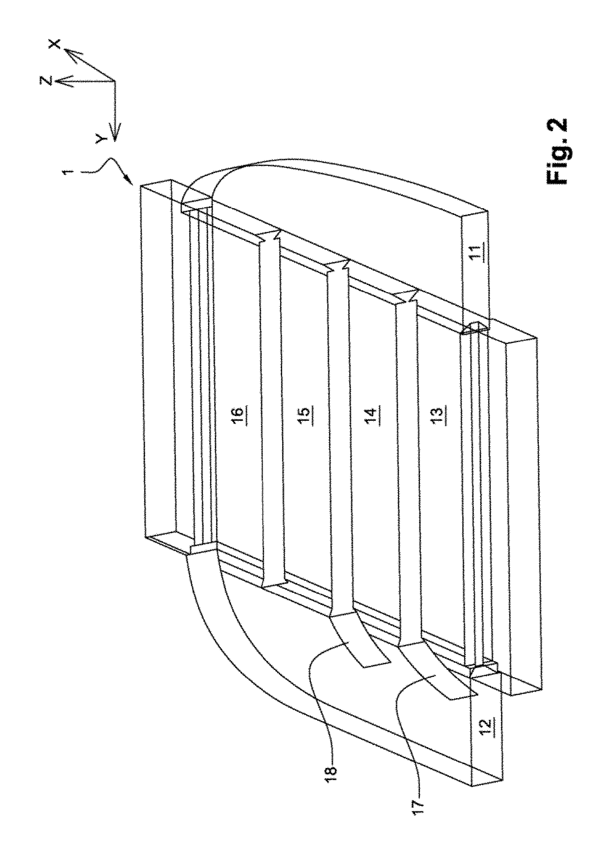
[0019]FIGS. 1 and 2 illustrate diagrammatically, in a top view and a perspective view respectively, an exemplary air conduit 1 according to the invention for cooling a battery pack. It is made of a material with a high thermal conductivity, a metal alloy for example, or else a plastic material. It is intended to be arranged in the battery pack (not shown on the figures), which may be made from a plastic material. The air conduit 1 comprises a mouth 11 for the entry of a fresh air flow FE. The inlet opening of the mouth 11 is intended to be housed in an opening made in the battery pack, in order to allow the entry of air into the pack via the mouth 11. The air conduit 1 also comprises a mouth 12 for the exit of a heated air flow FS. The outlet opening of the mouth 12 is intended to be housed in another opening made in the battery pack, in order to allow the exit of air from the pack via the mouth 12. The air conduit 1 finally comprises channels 13, 14, 15 and 16 which connect the inlet


PUM


Abstract

A conduit for cooling a heating element includes an inlet mouth for entry of a fresh air flow, a plurality of cooling channels, the fresh air flow dividing between the channels into a plurality of air flows to collect heat produced by the heating element, an outlet mouth for an exit of a heated air flow, the heated air flow resulting from a merger of the plurality of air flows after the heat collection, and air deflectors in the outlet mouth facing the channel outlets situated closest to an exit opening of the outlet mouth relative to the other channel outlets to prevent at least one of the plurality of air flows from exiting the cooling channels. The air deflectors extend over lengths which reduce as distances from the opening of the outlet mouth increase to guide the air flows towards the exit opening of the outlet mouth.

Description


Claims


Application Information

Patent Timeline
Owner RENAULT SA
Why Eureka
Try Eureka