Built-in cooling system

A cooling system, built-in technology, applied in the direction of metal processing equipment, maintenance and safety accessories, metal processing machinery parts, etc., can solve the problems of weight increase, bearing or gear transmission pair burning failure, large temperature control error, etc., to achieve Improve cooling efficiency and capacity, optimize structural design, effect of efficient cooling function

Active Publication Date: 2022-05-27
AVIC BEIJING AERONAUTICAL MFG TECH RES INST
View PDF10 Cites 0 Cited by
  • Summary
  • Abstract
  • Description
  • Claims
  • Application Information

AI Technical Summary

Problems solved by technology

The former is particularly affected by the ambient temperature, the cooling effect is not good, and the stability is poor
In the latter, the pipelines are intertwined and complicated, occupy a large space, and are prone to leakage. Also affected by the change of ambient temperature, the cooling effect is not ideal, and this leads to an increase in the size and weight of the milling head components, which greatly reduces the operation of the milling head. The dynamic response performance of the milling head also affects the integrity and aesthetics of the milling head
In addition, the main problem of the two methods is that the location where heat exchange occu

Method used


Image

  • Built-in cooling system
  • Built-in cooling system
  • Built-in cooling system

Examples


Embodiment Construction

[0030] The embodiments of the present invention will be described in further detail below with reference to the accompanying drawings and examples. The detailed description of the following embodiments and the accompanying drawings are used to exemplify the principles of the present invention, but not to limit the scope of the present invention, that is, the present invention is not limited to the described embodiments without departing from the spirit of the present invention. Any modifications, substitutions and improvements to parts, assemblies and connections are covered under.

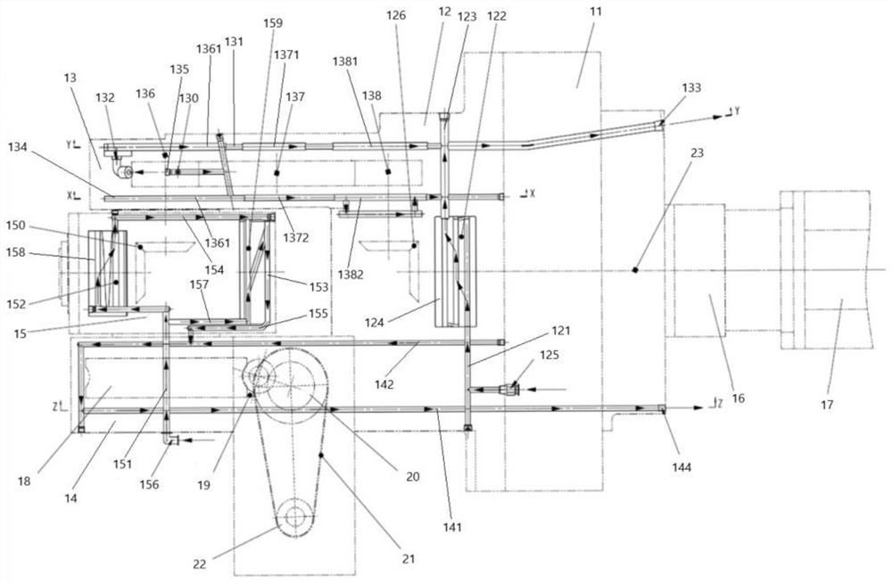
[0031] It should be noted that the embodiments in the present application and the features of the embodiments may be combined with each other under the condition of no conflict. The present application will be described in detail below with reference to the accompanying drawings and in conjunction with the embodiments. as attached figure 2 ~attached Image 6 As shown, the solid line is the inner


PUM


Abstract

The invention relates to a built-in cooling system, which is used for cooling a heavy load swing angle milling head, and comprises a sliding plate, a main box body fixedly arranged on the sliding plate, and a first box body, a second box body and a third box body which are arranged on the main box body and are communicated with one another, and the built-in cooling system comprises a first cooling channel arranged in the first box body; the second cooling channel is arranged in the second box body; the third cooling channel is arranged in the third box body, the fourth cooling channel is arranged in the main box body, the first cooling channel is communicated with the fourth cooling channel, and the second cooling channel is respectively communicated with the third cooling channel and the fourth cooling channel. According to the cooling system, the cooling channels of the cooling system are arranged in the corresponding box bodies, and the cooling channels are arranged in the heating areas in the corresponding box bodies, so that the cooling efficiency and capacity are effectively improved, and the cooling system is used for reducing the high temperature generated in the operation process of the heavy-load swing angle milling head; and the functional indexes, the machining precision and the operation stability of the heavy-load swing angle milling head are guaranteed.

Description


Claims


Application Information

Patent Timeline
Owner AVIC BEIJING AERONAUTICAL MFG TECH RES INST
Why Eureka
Try Eureka