Tower-type fresh milk freezing-type separation device

A separation device and technology for fresh milk, applied in milk processing equipment, other dairy products, dairy products, etc., can solve the problems of complex separator structure, inability to separate fresh milk, low separation efficiency of fresh milk and water, etc. Separation efficiency, simple device structure and low cost

Inactive Publication Date: 2020-06-02
李洋霞
View PDF0 Cites 0 Cited by
  • Summary
  • Abstract
  • Description
  • Claims
  • Application Information

AI Technical Summary

Problems solved by technology

[0003] At present, the structure of the separator of the fresh milk separator used in our country is complicated, and the separation ef

Method used


Image

  • Tower-type fresh milk freezing-type separation device
  • Tower-type fresh milk freezing-type separation device
  • Tower-type fresh milk freezing-type separation device

Examples


Embodiment Construction

[0017] The technical solution of this patent will be further described in detail below in conjunction with specific embodiments.

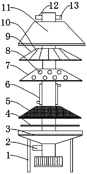
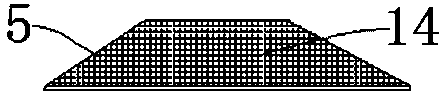
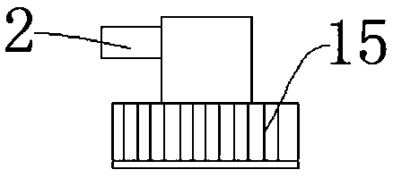
[0018] see Figure 1-3 , a tower-type fresh milk freezing type separation device, including a frame 1, an elastic sealing ring 4, a filter hole 8 and a discharge pipe 12, a feed pipe 2 is installed above the frame 1, and a separation pipe 2 is installed above the feed pipe 2 The bottom bracket 3 of the separator, the elastic sealing ring 4 is installed above the bottom bracket 3 of the separator, the trapezoidal filter cartridge 5 is arranged above the bottom bracket 3 of the separator, and the cooling passage 6 is installed above the trapezoidal filter cartridge 5, and the cooling passage 6 is composed of a draft pipe and It consists of a cooling jacket covering the outside of the draft tube; the jacket is connected to a cold water source (not shown) installed outside the frame through a circulation pipeline; a filter 7 is installed above the cooling


PUM


Abstract

The invention discloses a tower-type fresh milk freezing-type separation device. The device comprises a rack, an elastic sealing ring, filtering holes and a discharging pipe, wherein a feeding pipe isinstalled above the rack, a separator bottom support is installed above the feeding pipe, the elastic sealing ring is installed above the separator bottom support, a trapezoidal filter cartridge is arranged above the separator bottom support, a cooling channel is installed above the trapezoidal filter cartridge, and the cooling channel is composed of a through-flow pipe and a cooling jacket wrapping the outer side of the through-flow pipe; the jacket is connected to a cold water source mounted outside the rack through a circulating pipeline; and a filter is arranged above the cooling channel,the filtering holes are formed in the cooling channel and the filter, a centrifugal balance cover is installed above the filtering holes, a reinforcing rib is installed above the centrifugal balancecover, the upper portion of the reinforcing rib communicates with a top cover, the discharging pipe is installed above the top cover, a water outlet is formed in one side of the discharging pipe, a microporous membrane filter element is installed in the trapezoidal filter cartridge, and a rotary servo motor is installed below the separator bottom support.

Description


Claims


Application Information

Patent Timeline
Owner 李洋霞
Why Eureka
Try Eureka