Bubble film coiled material cutting, forming and stacking device

A coil cutting and stacking device technology, which is applied in metal processing and other directions, can solve the problems of high labor intensity and increased production costs, and achieve the effect of reducing labor and production costs

Pending Publication Date: 2019-09-17
河南达新源新材料有限公司
View PDF0 Cites 1 Cited by
  • Summary
  • Abstract
  • Description
  • Claims
  • Application Information

AI Technical Summary

Problems solved by technology

[0002] Bubble film is a kind of packaging material, which can reduce the impact and vibration. However, the bubble film is a roll material. In the actual use process, the bubble film needs to be cut into shape, a

Method used


Image

  • Bubble film coiled material cutting, forming and stacking device

Examples


Example Embodiment

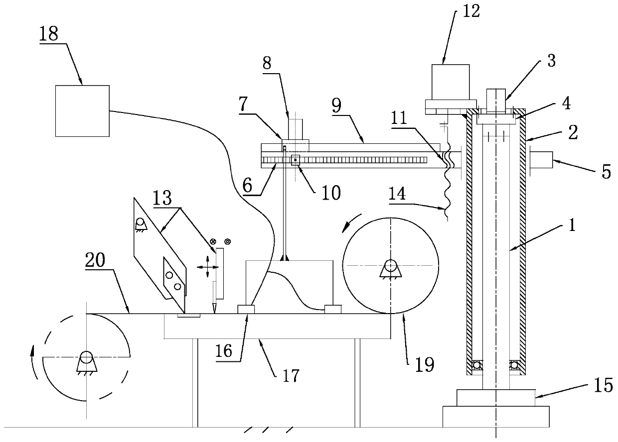
[0011] In order to further explain the technical means and effects of the present invention used to achieve the predetermined purpose, the specific implementation and structure of the foam film roll cutting and forming palletizing device proposed in accordance with the present invention will be given with reference to the accompanying drawings and preferred examples. , Characteristics and effects, detailed description is as follows.

[0012] See figure 1 , A foam film coil cutting and forming palletizing device, comprising a base 15, a sleeve 2, a first servo motor 3, an RV reducer 4 and a column 1 fixed on the base 15, and the sleeve 2 is sleeved on the column 1 On the outside, the column 1 and the sleeve hole 2 are connected by a bearing, the inner ring of the bearing is fixed to the column 1, the outer ring of the bearing is fixed to the sleeve 2, and the RV reducer 4 is fixed to the top of the column 1. The output shaft of the first servo motor 3 is connected to the input end o


PUM


Abstract

Disclosed is a bubble film coiled material cutting, forming and stacking device. The bubble film coiled material cutting, forming and stacking device comprises a base, a sleeve, a first servo motor, an RV reducer and a stand column which is fixed to the base. The sleeve is arranged on the outer side of the stand column through a bearing. An output shaft of the first servo motor is connected with the input end of the RV reducer. The RV reducer is fixedly connected with the stand column. The output end of the RV reducer is fixedly connected with the sleeve. A second servo motor is fixedly arranged on the outer side of the sleeve. An output shaft of the second servo motor is connected with a screw rod through a coupler. The screw rod is in threaded connection with a nut. The sleeve sleeves a swing arm. The swing arm is embedded with the nut. A guide rail and a rack are further arranged on the swing arm. A sliding block is arranged on the guide rail in a sliding mode. A third servo motor is fixedly arranged on the sliding block. An output shaft of the third servo motor is fixedly connected with a gear. The gear is meshed with the rack. An adsorption device is arranged at the bottom end of the sliding block and is electrically connected with a digital controller. As a result, automatic arrangement and placement of cut-formed bubble film sheets are realized.

Description


Claims


Application Information

Patent Timeline
Owner 河南达新源新材料有限公司
Why Eureka
Try Eureka