Electrode cylinder

A technology of electrode cylinder and cylinder, which is applied in the direction of ohmic resistance electrode, electric furnace heating, ohmic resistance heating parts, etc., can solve the problems of high electrode failure rate, slow electrode roasting, low electrode strength, etc., achieve good quality and reduce failure The effect of high rate and intensity

Pending Publication Date: 2019-10-15
阳江翌川金属科技有限公司
View PDF0 Cites 2 Cited by
  • Summary
  • Abstract
  • Description
  • Claims
  • Application Information

AI Technical Summary

Benefits of technology

This technology improves upon existing methods for manufacturing anodes used in batteries or other energy storage devices. By setting up certain areas where there're no openings at all during production, these improvements improve thermal conductivity while maintaining good bond between metal particles without adding extra steps like drilling through them after they have been formed into their final shape. Additionally, this method allows for faster formation of elec trodes with stronger bonds even if some parts break off due to poor weldability caused by insufficient coolant flow around them. Overall, this new process results in improved performance and reduced failures rates over time compared to older processes.

Problems solved by technology

Technics problem addressed in this patents relates to improving the efficiency and reliability of producing strong electrified elec trodes for use with submersible arc furnaces (SAF). Current methods involve melting or bending the elecrosis process through resistive heat from the rib platy that holds the material together. However, these techniques result in weakened areas near where there may break off due to insufficient coolant flow caused by poorly designed heat transfer channels within the rib structure. Additionally, current designs require large openings between the rib structures which results in slower burning time compared to traditional design.

Method used


Image

  • Electrode cylinder
  • Electrode cylinder
  • Electrode cylinder

Examples


Embodiment Construction

[0024] The technical solutions of the present invention will be further described in detail below in conjunction with the accompanying drawings and specific embodiments, so that those skilled in the art can better understand and implement the present invention, but the examples cited are not intended to limit the present invention.

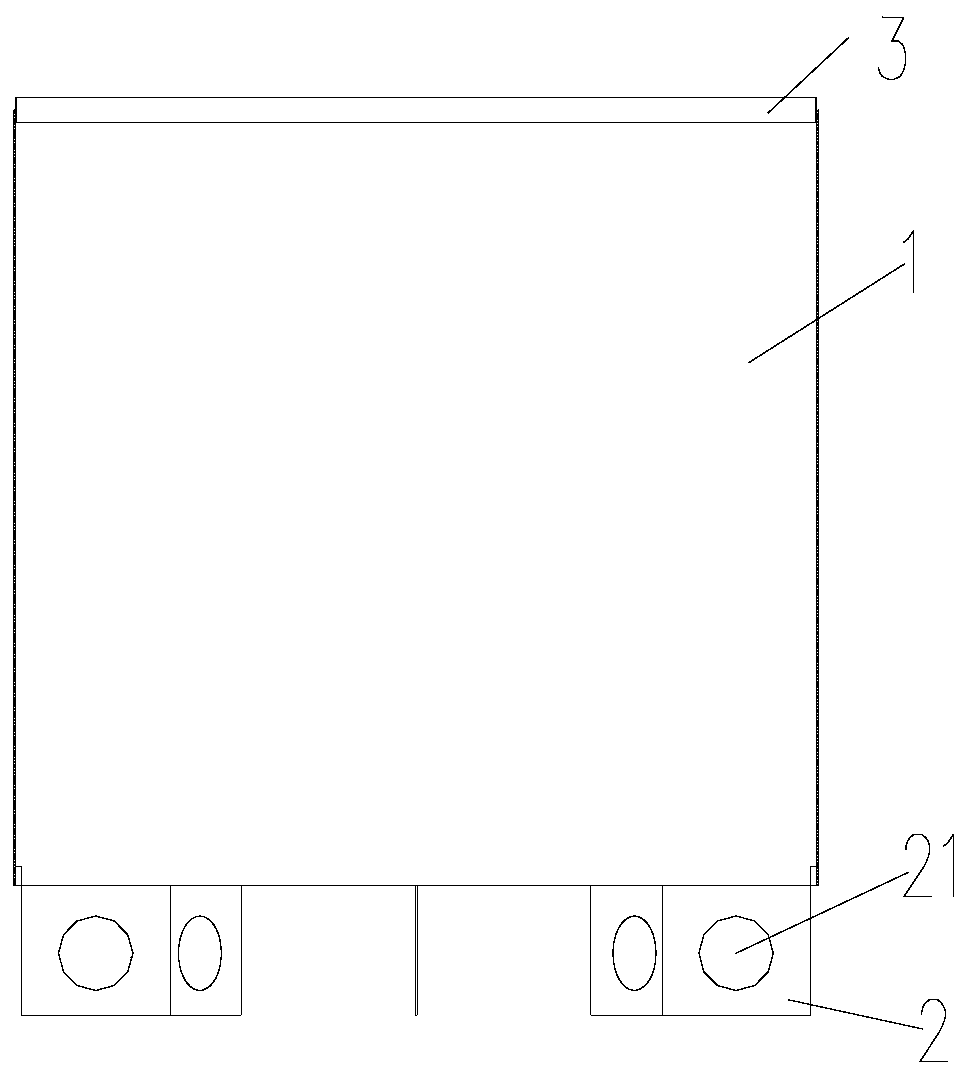
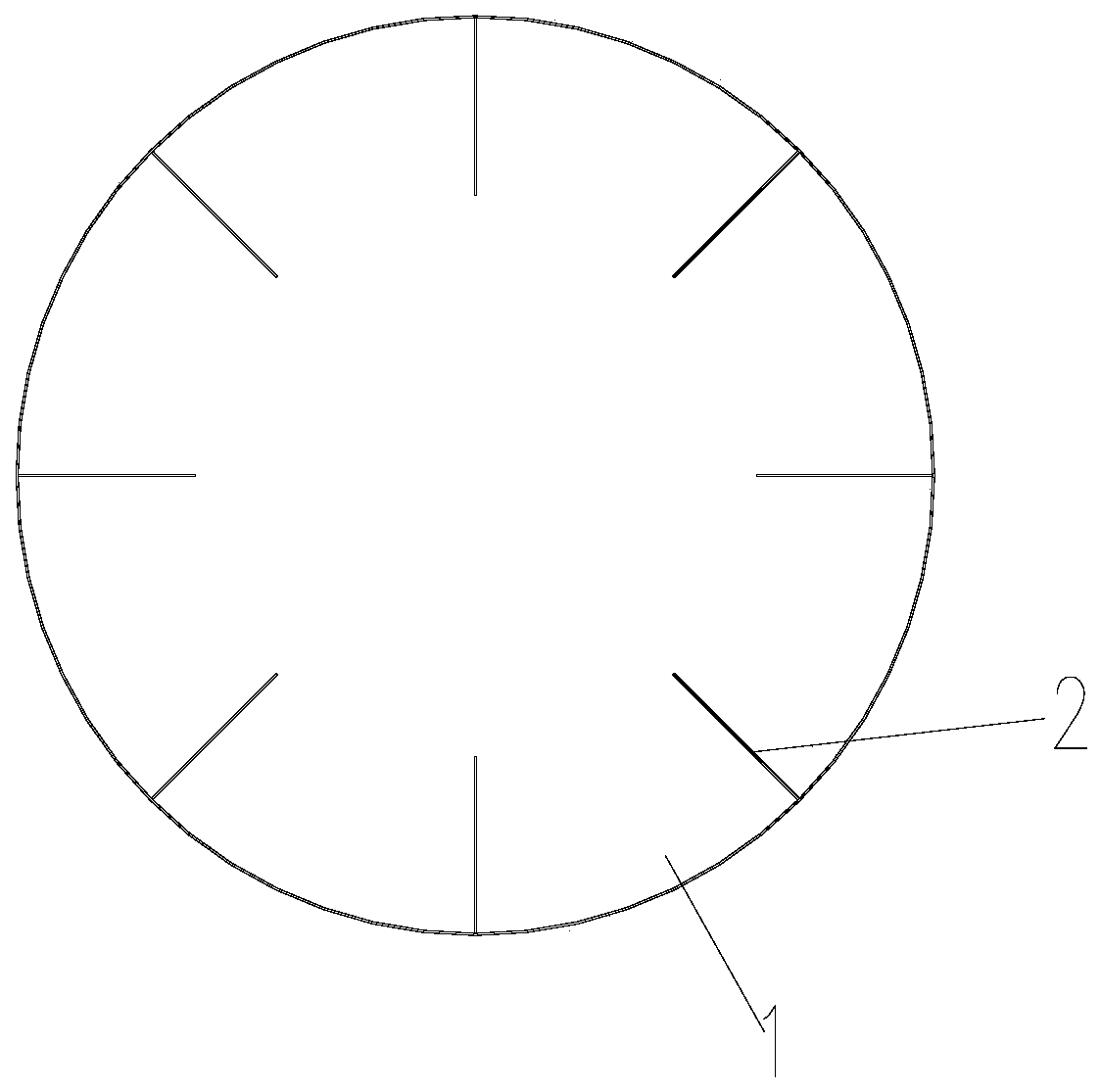
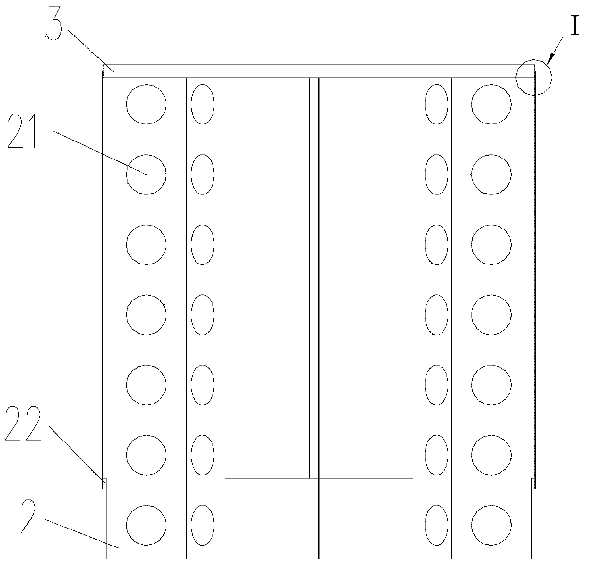
[0025] reference Figure 1-6 , The present invention provides an electrode cylinder, which is located in a submerged arc furnace, and a plurality of electrode cylinders are connected in series. In metal smelting, the electrode paste inside is sintered into electrodes. The electrode cylinder includes a cylindrical shape. The inner surface of the cylinder 1 is uniformly provided with a plurality of ribs 2 in the radial direction, so that the angle between the plurality of ribs 2 is constant, and the inner area of ​​the cylinder 1 can be evenly divided into multiple parts. The ribs 2 arranged in this way can make the heating more uniform and the heating sp


PUM

PropertyMeasurementUnit
Widthaaaaaaaaaa
Diameteraaaaaaaaaa
Pitchaaaaaaaaaa

Abstract

The invention discloses an electrode cylinder, which comprises a cylindrical cylinder body with open upper and lower sides. The inner surface of the cylinder body is uniformly provided with multiple ribs in a radial direction; the ribs extend towards the central axis direction of the cylinder body; one end of the rib is flush with the cylinder body and the other end protrudes against the cylinderbody; the rib is vertically provided with a row of multiple heat conduction holes; the ratio of the diameter of a heat conduction hole to the width of a rib is between 0.45 to 0.60; the ratio of a hole distance between adjacent heat conduction holes to the diameter of a heat conduction hole is between 1.6 to 1.65; and the distance between the top heat conduction hole and the top end of the rib andthe distance between the bottom heat conduction hole and the bottom end of the rib are both smaller than the diameter of a heat conduction hole. The heat conduction holes in the rib are arranged reasonably, the electrode sintering quality is better, the strength is higher, and accidents such as suspended paste before electrode sintering, head and block falling of the electrode, over slow electrode baking, soft and hard breaking of the electrode can be effectively solved.

Description


Claims


Application Information

Patent Timeline
Owner 阳江翌川金属科技有限公司
Why Eureka
Try Eureka