Electromagnetic shielding cooling device
An electromagnetic shielding and heat dissipation device technology, applied in the electronic field, can solve the problems of high cost and large space occupation, and achieve good electromagnetic shielding and heat dissipation effects
- Summary
- Abstract
- Description
- Claims
- Application Information
AI Technical Summary
Benefits of technology
Problems solved by technology
Method used
Image

Examples
no. 1 approach
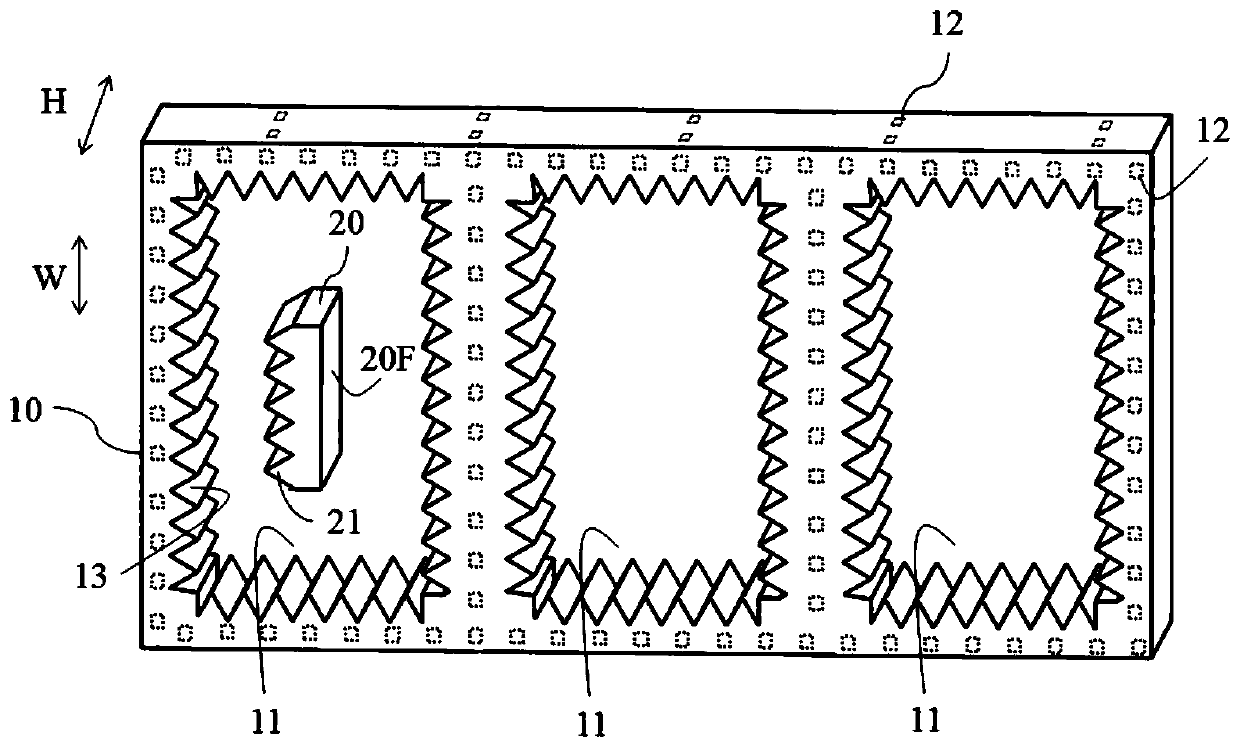
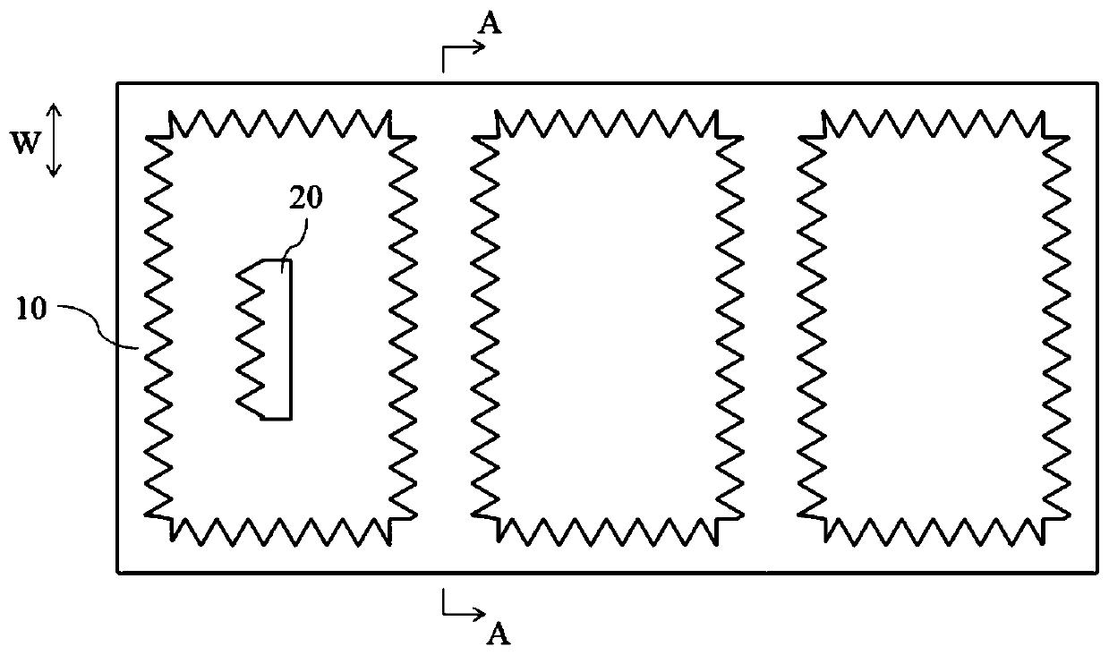
[0036] refer to figure 1 The electromagnetic shielding and heat dissipation device according to the first embodiment of the present invention is introduced.
[0037] The electromagnetic shielding heat dissipation device includes a frame body 10 . In this embodiment, the frame body 10 has three cylindrical shielding cavities 11 , and each shielding cavity 11 runs through the frame body 10 in the height direction H. As shown in FIG. The shielding cavity 11 is used for accommodating shielded objects such as PCB boards (not shown in the figure).
[0038] The frame body 10 is made of metal, so that the shielding cavity 11 has an electromagnetic shielding effect in the circumferential direction. Preferably, the material for making the frame body 10 includes one or more of copper, copper alloy, aluminum, aluminum alloy, titanium, and titanium alloy.
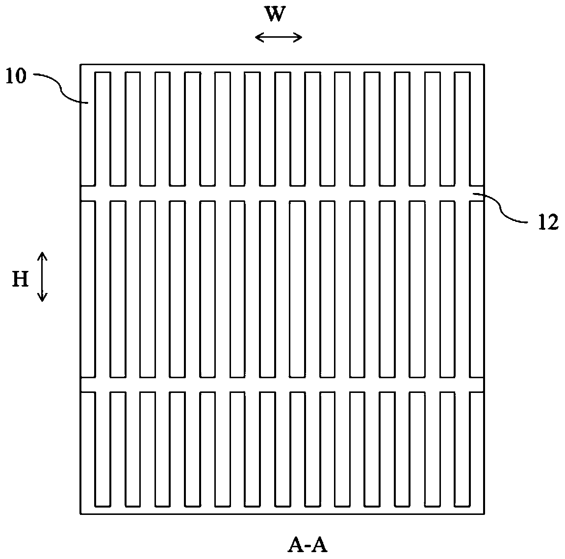
[0039] Several frame passages 12 are distributed inside the frame body 10 . The frame channel 12 is used to accommodate heat transfer
no. 2 approach
[0053] refer to Figure 4 An electromagnetic shielding and heat dissipation device according to a second embodiment of the present invention is introduced. The second embodiment is a modification of the first embodiment. Compared with the first embodiment, its improvement mainly lies in the addition of first fins 14 on the outer peripheral surface of the frame main body 10, and the installation of second fins on the surface of the first fins 14. Fin15. Figure 4 An exploded schematic view of the first fin 14 and the second fin 15 for connection to the frame body 10 is shown.
[0054] There are several first fin channels 141 inside the first fin 14 . The first fin passage 141 forms at least two first fin passage openings on the surface of each first fin 14 , and these two first fin passage openings are used to connect to the frame passage 12 on the surface of the frame main body 10 The two openings, so that the heat transfer medium in the frame passage 12 can flow through the f
no. 3 approach
[0059] refer to Figure 5 An electromagnetic shielding and heat dissipation device according to a third embodiment of the present invention is introduced. The third embodiment is a modification of the first embodiment, and its improvement compared with the first embodiment mainly lies in the addition of third fins 16 on the outer peripheral surface of the frame main body 10 .
[0060] A plurality of third fins 16 are connected to the outer peripheral surface of the frame body 10 in the form of an array. It should be understood that Figure 5 2 only schematically shows the solution of disposing the third fin 16 on one outer peripheral surface of the frame main body 10 . According to needs, third fins 16 may also be provided on other peripheral surfaces of the frame body 10 .
PUM
| Property | Measurement | Unit |
|---|---|---|
| Resistance | aaaaa | aaaaa |
Abstract
Description
Claims
Application Information
 - R&D Engineer
- R&D Manager
- IP Professional
- Industry Leading Data Capabilities
- Powerful AI technology
- Patent DNA Extraction
Browse by: Latest US Patents, China's latest patents, Technical Efficacy Thesaurus, Application Domain, Technology Topic.
© 2024 PatSnap. All rights reserved.Legal|Privacy policy|Modern Slavery Act Transparency Statement|Sitemap