Driving chip fault detection method, driving chip and main control chip

A technology of driving chip and main control chip, applied in the direction of measuring electricity, measuring device, measuring electrical variables, etc., can solve the problem of failure information not being sent to the main control chip, etc.

Pending Publication Date: 2019-12-20
FOSHAN SHUNDE MIDEA ELECTRICAL HEATING APPLIANCES MFG CO LTD
View PDF8 Cites 3 Cited by
  • Summary
  • Abstract
  • Description
  • Claims
  • Application Information

AI Technical Summary

Problems solved by technology

[0003] The IGBT driver chip is used to drive the IGBT to work. It is equipped with the function of detecting IGBT failure. When t

Method used


Image

  • Driving chip fault detection method, driving chip and main control chip
  • Driving chip fault detection method, driving chip and main control chip
  • Driving chip fault detection method, driving chip and main control chip

Examples


Embodiment Construction

[0051] Embodiments of the present invention are described in detail below, examples of which are shown in the drawings, wherein the same or similar reference numerals designate the same or similar elements or elements having the same or similar functions throughout. The embodiments described below by referring to the figures are exemplary and are intended to explain the present invention and should not be construed as limiting the present invention.

[0052] The fault detection method of the driver chip, the driver chip and the main control chip according to the embodiments of the present invention will be described below with reference to the accompanying drawings.

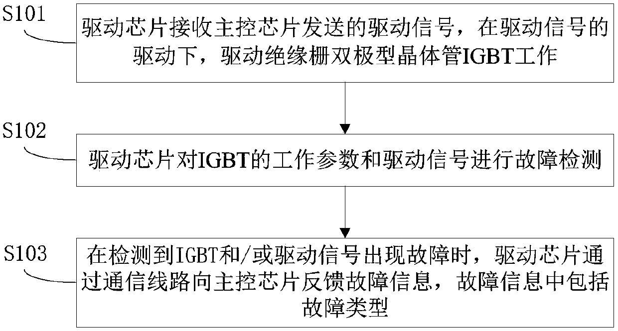
[0053] figure 1 It is a flowchart of a fault detection method for a driver chip according to an embodiment of the present invention.

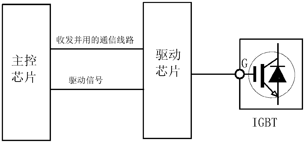
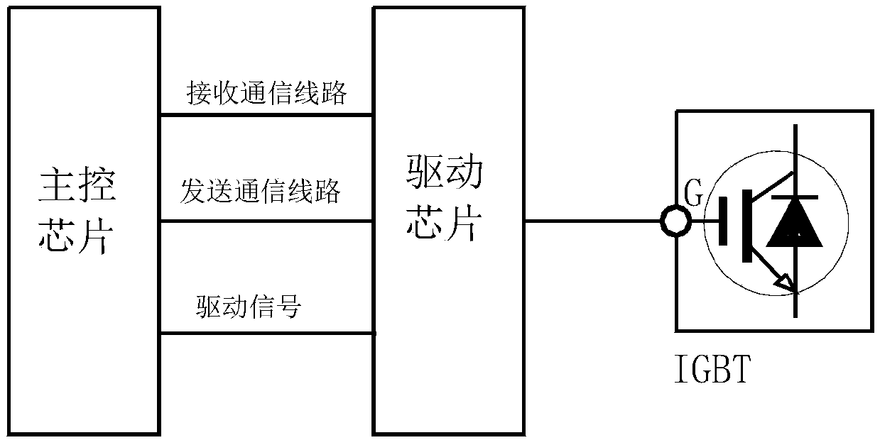
[0054] In an embodiment of the present invention, a communication line dedicated to transmitting information is provided between the driver chip and the main control chip.

[0055]


PUM


Abstract

The invention provides a driving chip fault detection method, a driving chip and a main control chip. A communication line special for information transmission is arranged between the driving chip andthe main control chip. The method comprises the steps that the driving chip receives a driving signal sent by the main control chip, and an insulated gate bipolar transistor (IGBT) is driven by the driving signal to work; the driving chip performs fault detection on working parameters of the IGBT and the driving signal; and when it is detected that the IGBT and/or the driving signal have/has a fault, the driving chip feeds fault information back to the main control chip through the communication line, wherein the fault information comprises a fault type. Therefore, the driving chip can feed the fault information back to the main control chip through the communication line.

Description


Claims


Application Information

Patent Timeline
Owner FOSHAN SHUNDE MIDEA ELECTRICAL HEATING APPLIANCES MFG CO LTD
Why Eureka
Try Eureka