Furnace wall of contaminated soil pyrolysis or incineration furnace

A technology that pollutes soil and incinerators, applied in incinerators, combustion chambers, combustion methods, etc., can solve the problems of reduced effective volume, inconvenient inspection of carbon deposits, complicated cleaning process, etc., and achieves the effect of easy reinstallation and simple and easy removal

Active Publication Date: 2019-12-27
深圳深态环境科技有限公司
View PDF7 Cites 0 Cited by
  • Summary
  • Abstract
  • Description
  • Claims
  • Application Information

AI Technical Summary

Problems solved by technology

It not only reduces the effective volume, but also is prone to clogging, which affects the processing efficiency
Carbon deposits are inconvenient to check, and CO2 and O2

Method used


Image

  • Furnace wall of contaminated soil pyrolysis or incineration furnace

Examples


Embodiment approach

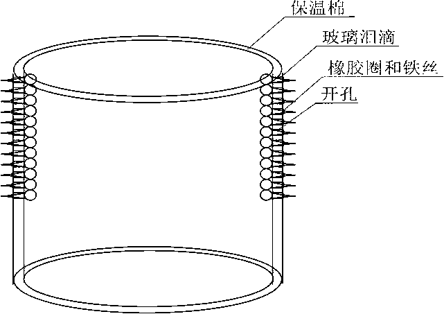
[0008] Implementation method: The sample is contaminated soil from a diesel storage tank. Use 2 cm thick aluminum silicate insulation cotton as the furnace wall with an inner diameter of 20 cm. Use a drilling machine to drill uniform and dense small holes on the furnace wall (covering the middle and upper parts of the furnace wall) , DN 3 mm, hole center spacing 1 cm. Use an alcohol lamp to melt the glass. When melting, it will naturally drop into ice water at 0°C under gravity to form tadpole-shaped glass teardrops. Select the one with a head diameter of about 1 cm and install it on the small hole on the left side of the furnace wall. The head is close to the furnace. On the inside of the wall, the tail protrudes outside, and the outside is fixed with rubber rings and iron wires. As a control, the aluminum silicate insulation wool was cut into a similar shape (head diameter about 1 cm, with a DN 3 mm tail), and installed on the small hole on the right side of the furnace wall.


PUM


Abstract

When pyrolysis or incineration treatment is adopted by the soil which is contaminated by organic matter, the smoke is prone to generating a carbon deposit on a furnace wall. The effective volume is reduced, the blockage is also prone to being caused, and the treatment efficiency is affected. The carbon deposit is not conveniently examined, CO2 and O2 sensors are often adopted to estimate the carbon deposit generation degree, the reliability is low, chemicals are mostly adopted to clean the carbon deposit away, and the cleaning process is complex. The invention provides a furnace wall of a contaminated soil pyrolysis or incineration furnace. The structure of the furnace wall can achieve the effects that no chemical exists, and the carbon deposit on the furnace wall is easily and instantly cleaned away; a worker just observes the furnace wall from the exterior or irradiates the furnace wall through lamplight so that the portion with the carbon deposit can be judged; only the portion withthe carbon deposit is cleaned away in a selective mode, and other portions are not involved; and the carbon deposit forming portion is induced.

Description


Claims


Application Information

Patent Timeline
Owner 深圳深态环境科技有限公司
Why Eureka
Try Eureka