Method and system for measuring uniform elongation of pipeline steel

A technology of pipeline steel and elongation rate, which is applied in the direction of testing the ductility of materials, measuring devices, and using stable tension/pressure to test the strength of materials, etc. It can solve the problems of low accuracy, expand the range, and ensure accurate fitting The effect of improving the measurement accuracy

Inactive Publication Date: 2019-12-31
SHOUGANG CORPORATION
View PDF6 Cites 0 Cited by
  • Summary
  • Abstract
  • Description
  • Claims
  • Application Information

AI Technical Summary

Benefits of technology

This patented technology allows researchers to study how well pipelines are made when they undergo various types of testing such as tension tests during manufacturing processes. By measuring these stresses over time it can help predict future performance issues with the pipe system being used. It provides accurate results that may aid engineers designing better materials and improving their overall effectiveness.

Problems solved by technology

This patented technical problem addressed in this patents relates to improving the performance of pipe lines used for transporting fluids under severe conditions like those found near extreme weather or when subjected to heavy loads during construction work. Existing designs with lower levels of resistance can lead to failures due to excessive bending forces that could cause cracks even if they were designed correctly. Therefore there has been interest towards new materials called stainless steels (SS) which provide better durability than regular carbon steel while still being able to maintain their effectiveness over long periods of service without losing its ability to resist corrosion attacks from various substances commonly known collectively as sour crude oils).

Method used


Image

  • Method and system for measuring uniform elongation of pipeline steel
  • Method and system for measuring uniform elongation of pipeline steel
  • Method and system for measuring uniform elongation of pipeline steel

Examples


Embodiment 1

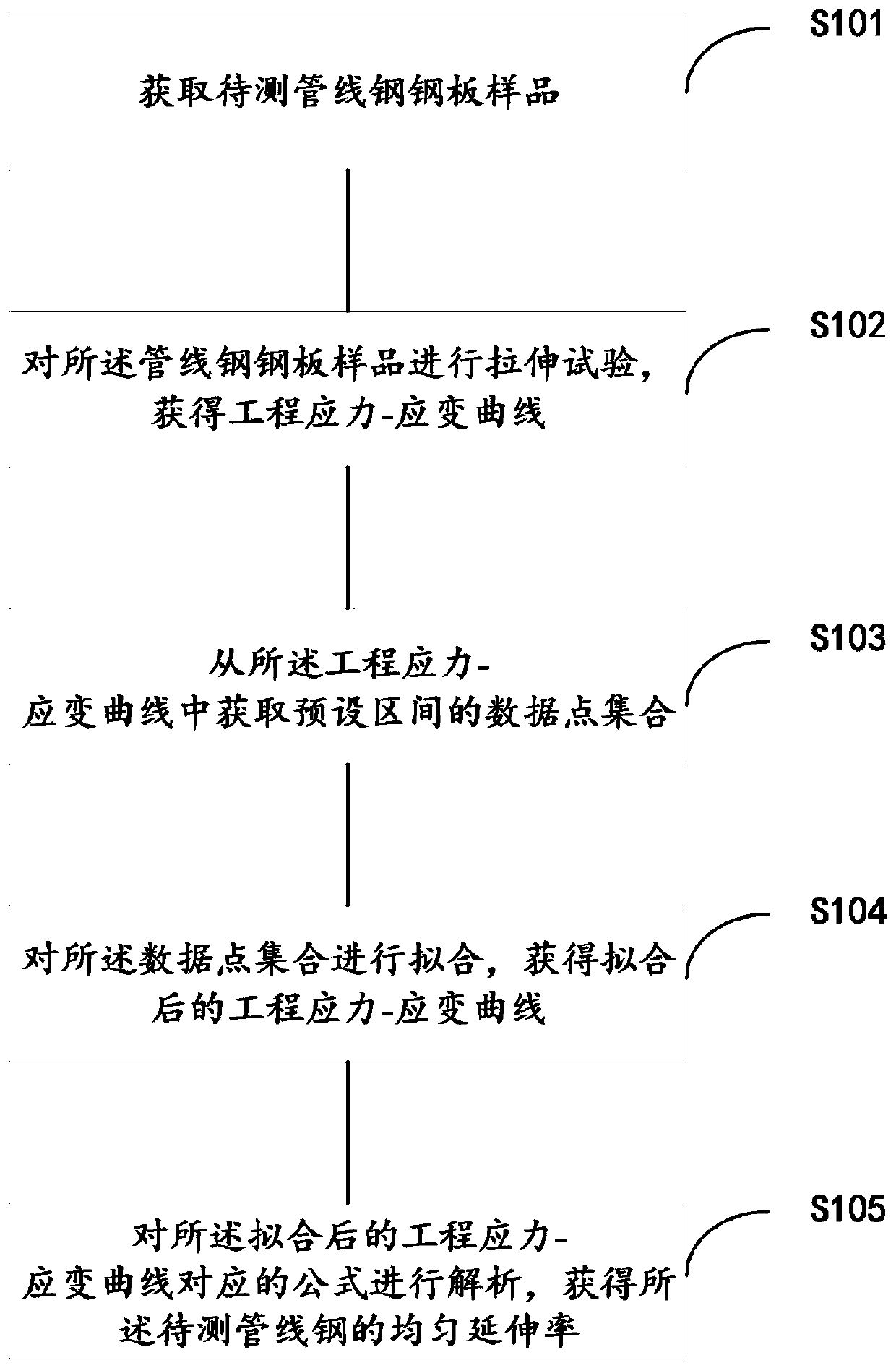
[0042] In this embodiment, a method for measuring the uniform elongation of pipeline steel, see figure 1 , the method includes the following steps:

[0043] S101. Obtain a sample of the pipeline steel plate to be tested;

[0044] S102. Perform a tensile test on the pipeline steel plate sample to obtain an engineering stress-strain curve;

[0045] S103. Obtain a set of data points in a preset interval from the engineering stress-strain curve; wherein, the starting point of the preset interval is the data point corresponding to a strain of 0.5%, and the end point is the strain value corresponding to the maximum stress value increased by 1 The data point corresponding to the -2% strain point;

[0046] S104. Fitting the set of data points to obtain a fitted stress-strain curve;

[0047] S105. Analyzing the formula corresponding to the fitted stress-strain curve to obtain the uniform elongation of the pipeline steel to be tested.

[0048] In the following, taking the measurement of

Embodiment 2

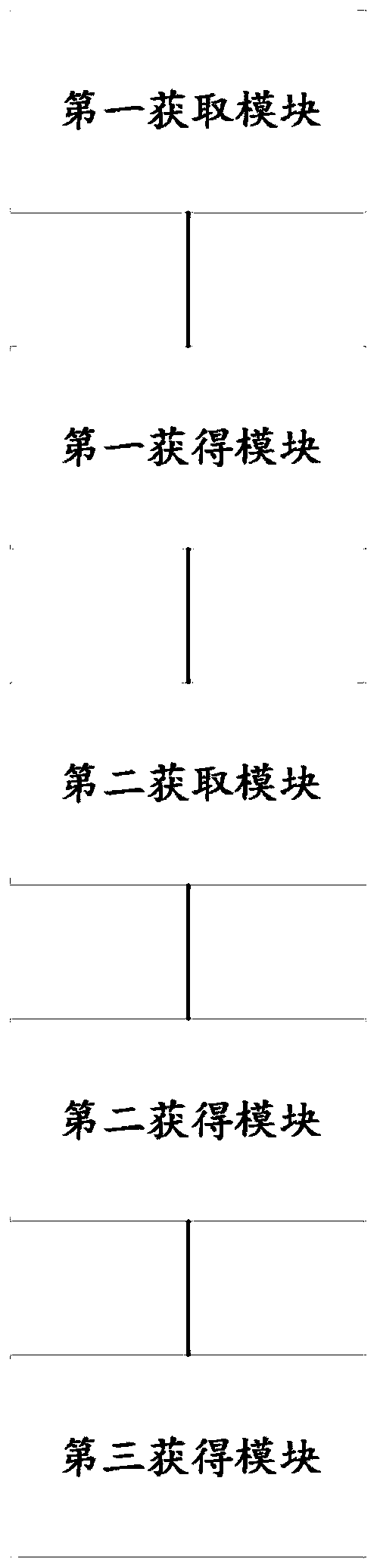
[0067] In this embodiment, a system for measuring the uniform elongation of pipeline steel, see figure 2 , the system includes:

[0068] The first obtaining module is used to obtain the steel plate sample of the pipeline to be tested;

[0069] The first obtaining module is used to perform a tensile test on the pipeline steel plate sample to obtain an engineering stress-strain curve;

[0070] The second acquisition module is used to acquire a set of data points in a preset interval from the engineering stress-strain curve; wherein, the starting point of the preset interval is the data point corresponding to a strain of 0.5%, and the end point is corresponding to the maximum stress value The strain value increases by 1-2% to the data point corresponding to the strain point;

[0071] The second obtaining module is used to fit the set of data points to obtain a fitted stress-strain curve;

[0072] The third obtaining module is configured to analyze the formula corresponding to th


PUM


Abstract

The invention discloses a method and system for measuring the uniform elongation of pipeline steel. The method comprises the following steps that: a to-be-measured pipeline steel plate sample is acquired; a tensile test is carried out on the pipeline steel plate sample, so that an engineering stress-strain curve can be obtained; a data point set of a preset interval is obtained from the engineering stress-strain curve, the starting point of the preset interval is a data point corresponding to strain of 0.5%, and the terminal point of the preset interval is a data point corresponding to a strain point of which the strain value corresponding to a maximum stress value is increased by 1-2%; the data point set is fitted, so that a fitted stress-strain curve can be obtained; and a formula corresponding to the fitted stress-strain curve is analyzed, so that the uniform elongation of the to-be-measured pipeline steel is obtained. With the method and system adopted, the technical problem that the result accuracy of an existing method for measuring the uniform elongation of pipeline steel is low can be solved.

Description


Claims


Application Information

Patent Timeline
Owner SHOUGANG CORPORATION
Why Eureka
Try Eureka