Computer mainframe dust removal device

A dust removal device and computer technology, which is applied in the field of computers, can solve problems such as difficult cleaning, time-consuming and labor-intensive, and reduced service life of computers, and achieve the effects of saving space, saving water resources, and preventing dust from floating

Active Publication Date: 2020-01-24
杭州谷钉纹信息技术有限公司
View PDF8 Cites 3 Cited by
  • Summary
  • Abstract
  • Description
  • Claims
  • Application Information

AI Technical Summary

Problems solved by technology

[0002] As an indispensable tool in today's life, the computer is inseparable from learning, work or entertainment. However, with the prolongation of use time, a large amount of dust often accumulates inside the computer mainframe. This dust will not only cause the mainframe to overheat, The service life o

Method used


Image

  • Computer mainframe dust removal device
  • Computer mainframe dust removal device
  • Computer mainframe dust removal device

Examples


Example Embodiment

[0019] The present invention will be further described below in conjunction with the description of the drawings and the embodiments. The manner of the present invention includes but is not limited to the following embodiments.

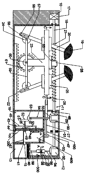
[0020] Such as Figure 1-5 As shown, a dust removal device for a computer mainframe includes a body 10 in which a working cavity 11 with an upward opening is provided, and a rotatable motor spindle 18 is provided in the working cavity 11, and the motor spindle 18 The upper part is fixedly provided with a thread 21, the thread 21 is threadedly fixed with a first threaded sleeve 28, the lower end of the first threaded sleeve 28 is fixedly provided with a threaded fixing block 65, the threaded fixing block 65 is symmetrically provided with a fixing outer Frame 25, the fixed outer frame 25 is fixedly provided with a swing shaft 66, the swing shaft 66 can swing left and right with a cleaning brush link 20, the upper end of the cleaning brush link 20 is fixed with


PUM


Abstract

A computer mainframe dust removal device comprises a machine body. A working cavity with an upward opening is formed in the machine body, a rotatable motor main shaft is arranged in the working cavity, and threads are fixedly formed in the motor main shaft. A first threaded sleeve is fixedly arranged on the threads in a threaded mode, a first transition bevel gear is fixedly arranged at the lowerend of the first threaded sleeve, an outer fixing frame is arranged on the first transition bevel gear in a left-and-right symmetry mode, and a dust discharging pipe is fixedly arranged in the outer fixing frame. According to the computer mainframe dust removal device, the dust can be separated from the inner wall of a mainframe through dust removal brushes, then the dust is collected by a dust absorption pump, the phenomenon that after the dust drops down, the secondary pollution is caused is avoided, dust clusters which are originally fluffy are wetted and contracted through water addition,and therefore the effect of saving the space is achieved; and then the contracted dust is collected, and the unnecessary water which exists after the dust clusters are wetted is filtered by a filtering screen and then is subjected to secondary utilization through a water suction pump.

Description


Claims


Application Information

Patent Timeline
Owner 杭州谷钉纹信息技术有限公司
Why Eureka
Try Eureka