Screw polishing machine

A polishing machine and screw technology, which is applied to surface polishing machine tools, grinding/polishing equipment, and parts of grinding machine tools, etc. It can solve the problems of large screw output, inability to polish threads, and low screw polishing efficiency.

Inactive Publication Date: 2020-01-24
海盐天奇标准件股份有限公司
View PDF12 Cites 3 Cited by
  • Summary
  • Abstract
  • Description
  • Claims
  • Application Information

AI Technical Summary

Problems solved by technology

[0004] After the screw is produced, it needs to be polished. However, the output of the screw is relatively large, and

Method used


Image

  • Screw polishing machine
  • Screw polishing machine
  • Screw polishing machine

Examples


Embodiment Construction

[0026] The following descriptions are only preferred implementations of the present invention, and the scope of protection is not limited to this embodiment. All technical solutions under the idea of ​​the present invention shall belong to the scope of protection of the present invention. At the same time, it should be pointed out that for those skilled in the art, some improvements and modifications without departing from the principle of the present invention should also be regarded as the protection scope of the present invention.

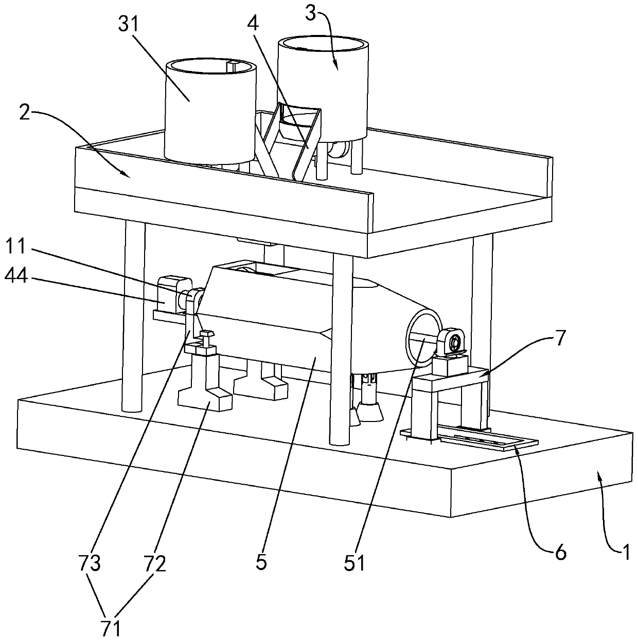
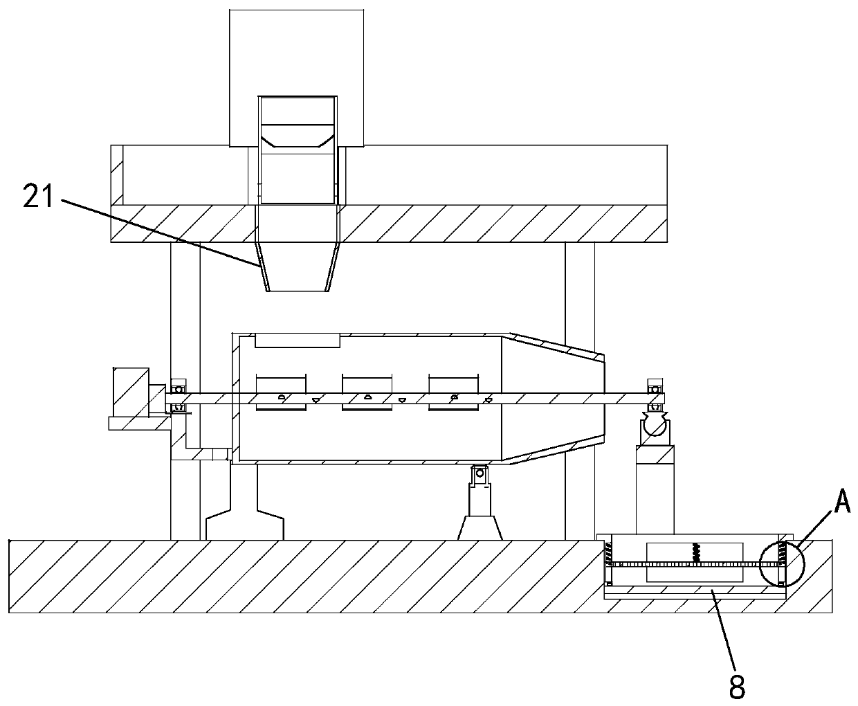
[0027] like figure 1 and Figure 4 As shown, a screw polishing machine includes a frame 1, the upper end of the frame 1 is provided with a loading table 2, and two feeding frames 3 are symmetrically provided on the loading table 2. One side of the feed frame 3 is provided with a material guide 4, and the material guide 4 is inclined. The feeding frame 3 includes a storage tray 31 and a vibrating plate 32 , an outlet is provided on one side of the


PUM


Abstract

The invention discloses a screw polishing machine. The screw polishing machine comprises a frame; a loading table is arranged at the upper end of the frame; the lower end of the loading table is connected with a feed cylinder; two feed frames are symmetrically arranged on the loading table; guide ways are arranged on one sides of the feed frames; baffle plates are arranged on one sides of the feedframes; push plates are arranged on the baffle plates; first cylinders are arranged on the feed frames, and are fixedly connected with the push plates; support bases are arranged on the two sides o fthe frame, and are provided with polishing cylinders; the polishing cylinders are provided with feed ports; connecting columns are arranged in the polishing cylinders; the support bases are arrangedon one side of the frame; first motors are arranged on the support bases; output shafts of the first motors are fixedly connected with one ends of the connecting columns; and stirring blades are fixedly arranged on the connecting columns. The screw polishing machine is reasonable in structure; sand and screws needing to be polished are placed on the two feed frames; the first cylinders control theobjects in the two feed frames to feed in the polishing cylinders; and the polishing cylinders stir the sand and the screws therein to rub the sand on the surfaces of the screws so as to polish the screws.

Description


Claims


Application Information

Patent Timeline
Owner 海盐天奇标准件股份有限公司
Why Eureka
Try Eureka