Clamping device for plug-in unit

A plug-in and gripper technology, which is applied in the field of plug-in clamping devices, can solve problems that affect the efficiency of circuit board space utilization

Active Publication Date: 2020-02-21
CHICONY POWER TECH CO LTD
View PDF4 Cites 4 Cited by
  • Summary
  • Abstract
  • Description
  • Claims
  • Application Information

AI Technical Summary

Problems solved by technology

In order to ensure that the jaws 4 can be operated, this distance is often limited by the operating space S of the jaws 4 and cannot be reduced arbitrarily, which affects the space utilization efficiency on the circuit board

Method used


Image

  • Clamping device for plug-in unit
  • Clamping device for plug-in unit
  • Clamping device for plug-in unit

Examples


Embodiment Construction

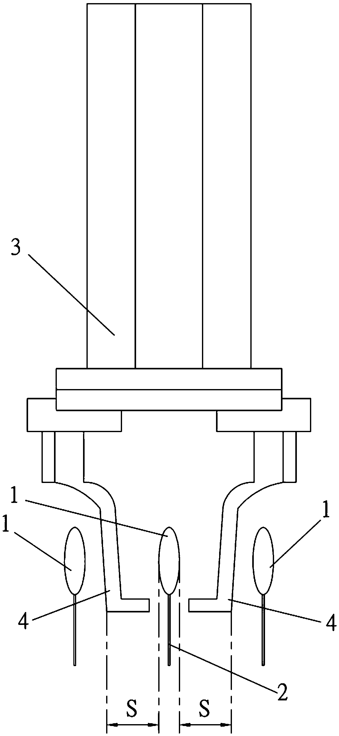
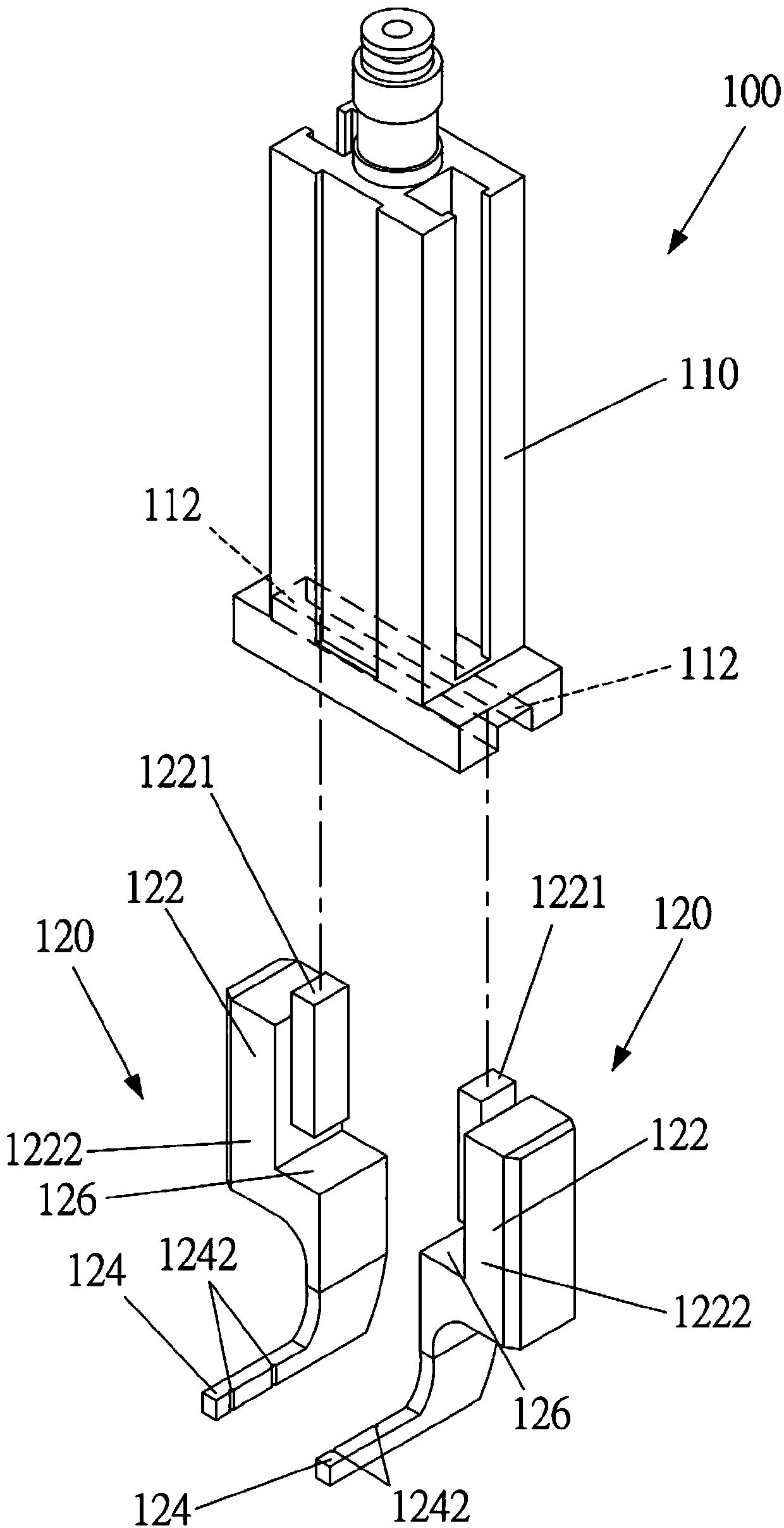
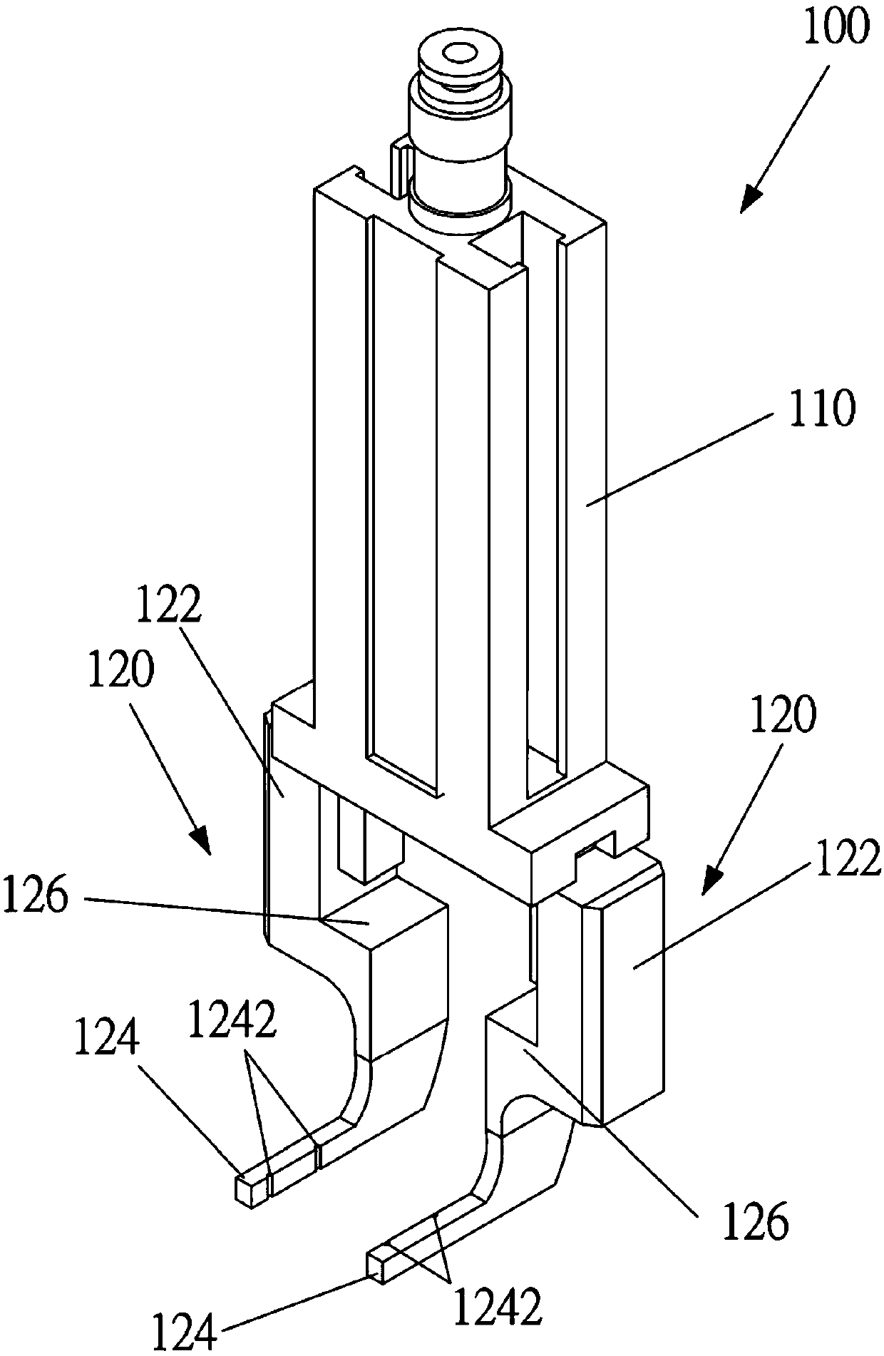
[0049] See attached figure 2 , attached image 3 and attached Figure 4 Shown is a clamping device 100 for inserts according to the first embodiment of the present invention. Insertion refers to the operation of inserting the pin 220 of the electronic component 200 into the conductive through hole 310 (Platating Through Hole) of the circuit board 300 . The aforementioned electronic component 200 includes a body 210 and a plurality of pins 220 ; a specific embodiment of the electronic component 200 is a ceramic capacitor, which has a flat body 210 and two parallel pins 220 . The clamping device 100 is used for clamping the electronic component 200 from the feeding mechanism or the feeding tray, placing the electronic component 200 on a circuit board 300 , and inserting the pin 220 into the conductive through hole 310 of the circuit board 300 . Subsequent soldering is performed to fix the pins 220 to the conductive through holes 310 , so that the electronic components 200 an...


PUM


Abstract

The invention provides a clamping device for a plug-in unit. The device comprises a driving assembly and two clamping jaws, wherein the two clamping jaws are connected with the driving assembly, the driving assembly drives at least one of the two clamping jaws to move in the horizontal driving direction to get close to each other, the two clamping jaws are respectively provided with a vertical part and a clamping part, the vertical part is provided with a first end and a second end, the first end is connected with the driving assembly, and the clamping part is connected with the second end, the clamping parts of the two clamping jaws are arranged in parallel and are perpendicular to the horizontal driving direction. The clamping device for the plug-in unit is advantaged in that the operation space reserved for the clamping jaws by the front side face and the rear side face of a body of an electronic element can be effectively reduced.

Description

technical field [0001] The invention relates to gripping devices, in particular for inserts. Background technique [0002] The current plug-in operation of the circuit board, that is, the operation of inserting the connecting pin 2 of the electronic component 1 into the conductive through hole of the circuit board, is performed by a plug-in device. The plug-in device is equipped with a gripper 4 driven by a pneumatic cylinder 3, and the electronic component 1 is clamped by the feeding mechanism, and the electronic component 1 is moved to the circuit board to insert the pin 2 into the corresponding conductive through hole, and then the electronic component 1 is released. circuit board. [0003] attached figure 1 Taking a ceramic capacitor as an example of the electronic component 1, the ceramic capacitor has a flat body. The two clamping jaws 4 extend downwards and extend horizontally towards each other, so as to clamp the body from two flat sides of the electronic compone...

Claims


Application Information

Patent Timeline
IPC IPC(8): H05K13/04H05K3/30
CPCH05K3/306H05K13/0404
Inventor 黄树藩
Owner CHICONY POWER TECH CO LTD
Why Eureka
Try Eureka