Single-stage energy storage converter and control method thereof
An energy storage converter, a single-stage technology, applied in the field of energy storage converters, can solve problems such as failures, deterioration of control performance, failure to realize cascade utilization of batteries, etc., to improve reliability, increase application range, reduce The effect of small input cost
- Summary
- Abstract
- Description
- Claims
- Application Information
AI Technical Summary
Problems solved by technology
Method used
Image

Examples
Example Embodiment
[0036] Example one
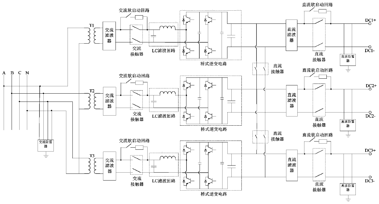
[0037] In one or more embodiments, a single-stage energy storage converter with an isolation transformer is disclosed, such as figure 1 As shown, each phase of the single-stage energy storage converter is separately connected to a transformer for isolation, which directly converts alternating current into direct current to charge the battery, while discharging and connecting the battery to the grid. The single-stage energy storage converter can realize the regulation of the DC output voltage. And the current adjustment function. The AC end of the single-stage energy storage converter is connected to the AC grid A, B, C, and N. The DC end has three sets of connecting terminals, and each set of terminals can be connected to the battery; the AC end is connected with an AC lightning protection device, for single-stage The energy storage converter plays a role of lightning protection.
[0038] Taking the A-phase circuit structure as an example, the transformer T1 play
Example Embodiment
[0043] Example two
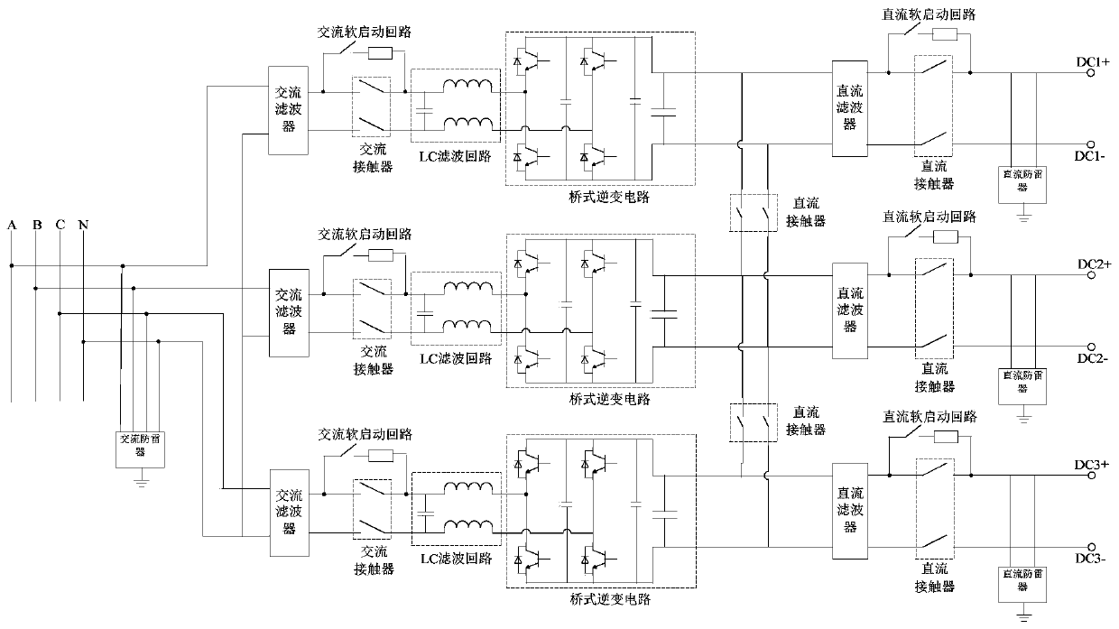
[0044] In one or more embodiments, a single-stage energy storage converter without an isolation transformer is disclosed, with reference to figure 2 As shown, one end of each phase AC filter of the single-stage energy storage converter is connected to N at the same time, and the other end of each phase AC filter is connected to the grid A, B, and C respectively to achieve transformerless isolation For the single-stage energy storage converter, other circuit connection relationships are the same as those described in the first embodiment, and the description will not be repeated here.
[0045] In other embodiments, in figure 2 In the connection mode shown, changing the connection relationship between the power grid and the AC filter can easily realize the three-phase three-wire power supply. figure 2 The AC filter of the single-stage energy storage converter shown is connected first and last, that is, the filter is connected in a triangular connection relationshi
Example Embodiment
[0046] Example three
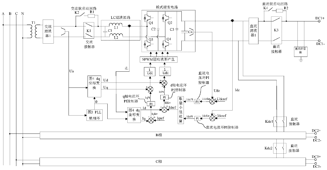
[0047] In one or more embodiments, a control method of a single-stage energy storage converter is disclosed, refer to image 3 ,include:
[0048] Take the A-phase control process as an example. The energy storage converter is connected to the grid through an AC filter and transformer T1. The DC side DC1+ and DC1- are connected to the positive and negative poles of the battery, while DC2+ and DC2-, DC3+ and DC3- are connected to the battery. The model and voltage level of the battery connected to DC1+ and DC1- are different.
[0049] Since the three-phase DC output terminal is connected to batteries of different models and voltage levels, when the energy storage converter is powered on, first ensure that Kdc1 and Kdc2 are disconnected, and ensure that the DC busbars are independent. The three-phase separate charge and discharge voltage and current of the battery control;
[0050] Then enter the soft-start phase, the auxiliary AC contactor K2 is closed, the soft-sta
PUM
 Abstract
Description
Claims
Application Information
 - R&D Engineer
- R&D Manager
- IP Professional
- Industry Leading Data Capabilities
- Powerful AI technology
- Patent DNA Extraction
Browse by: Latest US Patents, China's latest patents, Technical Efficacy Thesaurus, Application Domain, Technology Topic.
© 2024 PatSnap. All rights reserved.Legal|Privacy policy|Modern Slavery Act Transparency Statement|Sitemap