Fuel cell structure

A fuel cell and power terminal technology, which is applied to fuel cells, fuel cell components, circuits, etc., can solve the problems of energy waste, ineffective use of other spaces on the floor, high energy consumption, etc., and achieves short axial heat dissipation distance. The effect of improving space and large heat dissipation area

Active Publication Date: 2020-04-21
CHINA FIRST AUTOMOBILE
View PDF6 Cites 2 Cited by
  • Summary
  • Abstract
  • Description
  • Claims
  • Application Information

AI Technical Summary

Benefits of technology

This patented technology describes a new design for a type of battery called a proton exchange membraneless (PEM) power source used on vehicles. It achieves this by arranging different types of cells together into arrays instead of just one row or column like traditional batteries. By doing away from regular arrangement, these PEMs have greater surface areas than previous designs while still providing better cool performance compared to older methods such as lithium-ion chemistry.

Problems solved by technology

The technical problem addressed in this patented text relates how current methods of forming conventional fuel battery systems result in wasted energy due to their bulky size or limited placement options within certain areas on the car's interior design.

Method used


Image

  • Fuel cell structure
  • Fuel cell structure
  • Fuel cell structure

Examples


Embodiment Construction

[0062] The present invention will be further described in detail below in conjunction with the accompanying drawings and embodiments. It should be understood that the specific embodiments described here are only used to explain the present invention, but not to limit the present invention. In addition, it should be noted that, for the convenience of description, only some structures related to the present invention are shown in the drawings but not all structures.

[0063] In the description of the present invention, unless otherwise clearly specified and limited, the terms "connected", "connected" and "fixed" should be understood in a broad sense, for example, it can be a fixed connection, a detachable connection, or an integrated ; It can be a mechanical connection or an electrical connection; it can be a direct connection or an indirect connection through an intermediary, and it can be the internal communication of two components or the interaction relationship between two com


PUM


Abstract

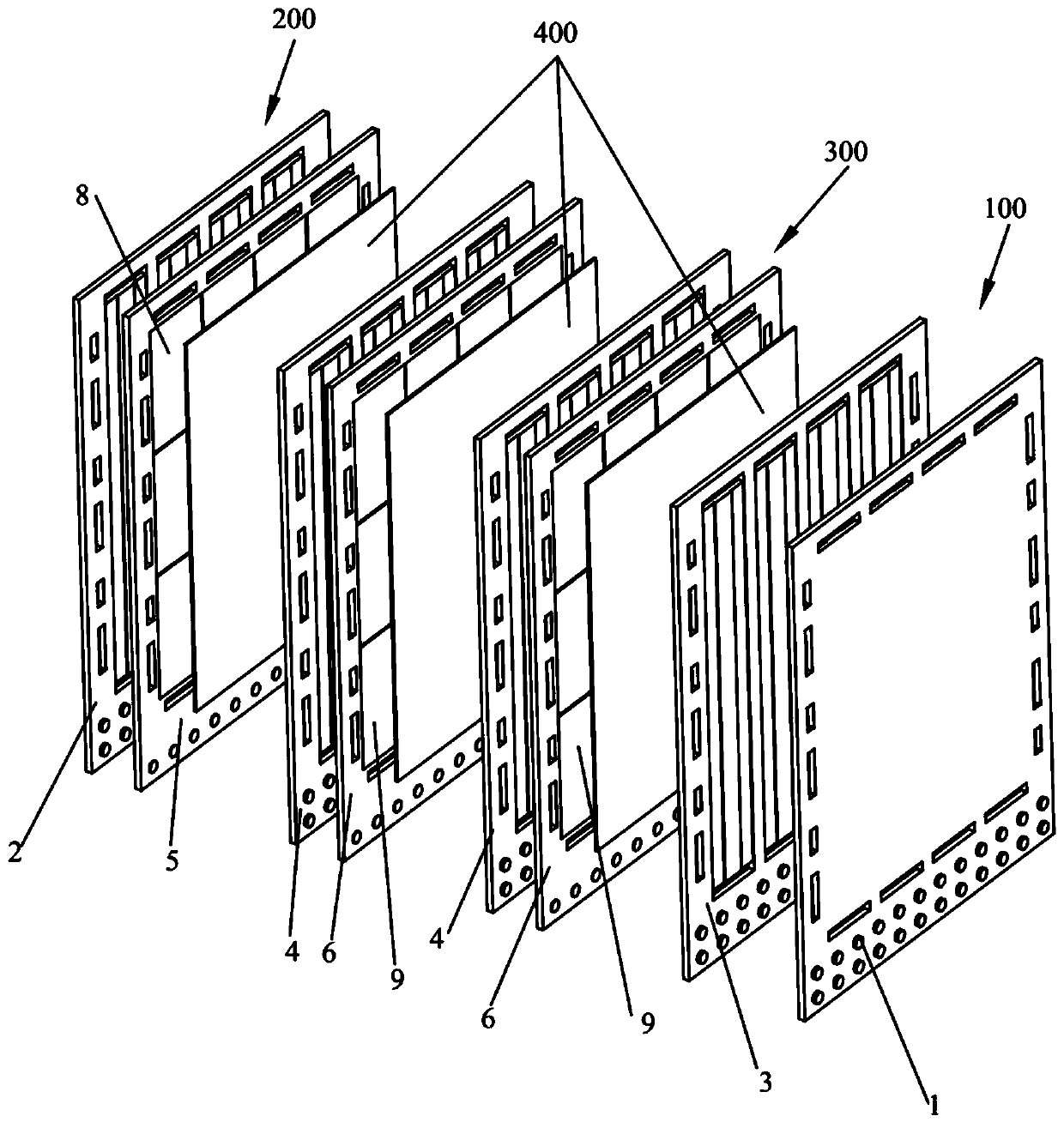
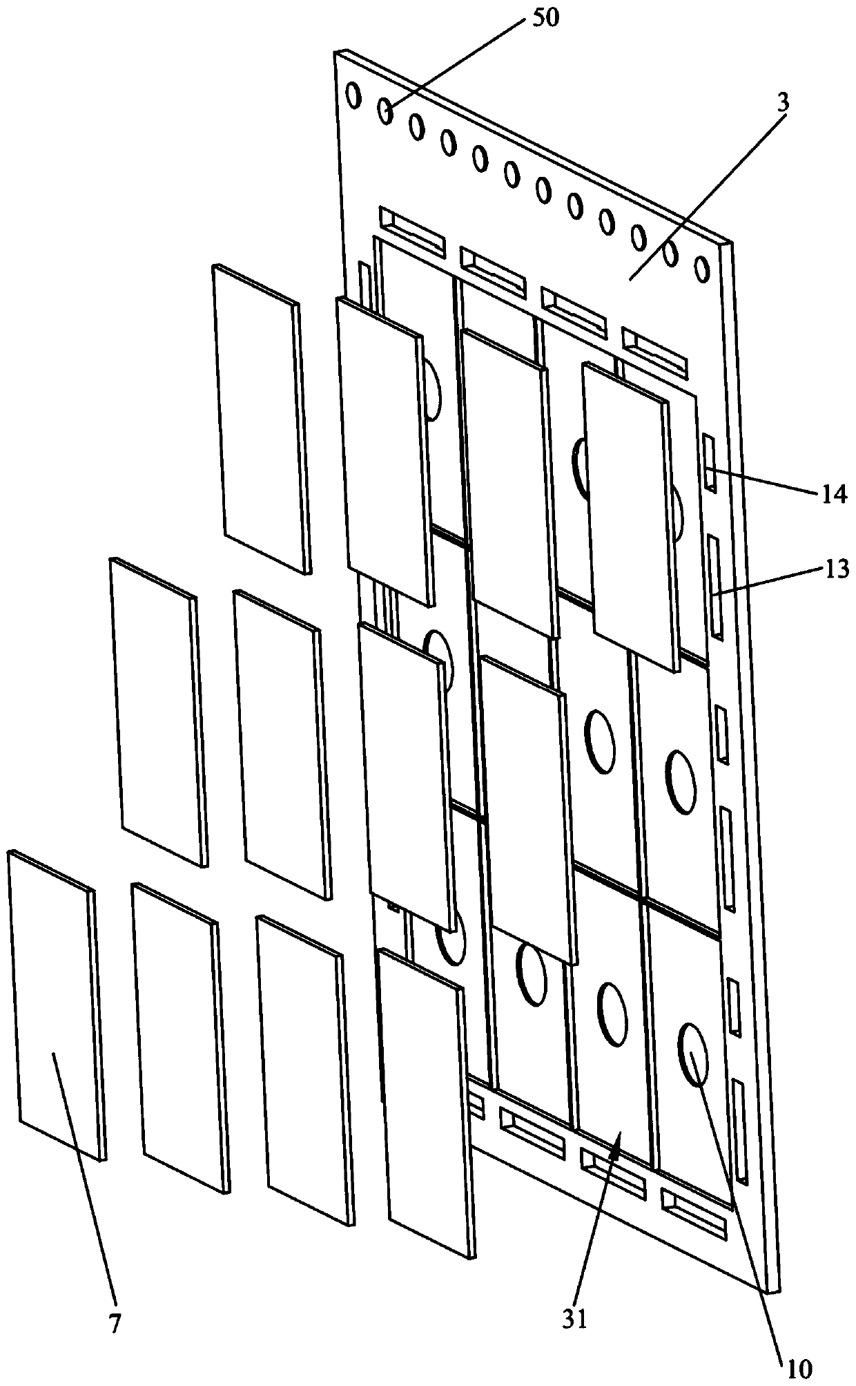
The invention relates to the technical field of new energy, and particularly discloses a fuel cell structure. The fuel cell structure comprises an anode end plate matrix assembly, a cathode end platematrix assembly, a bipolar plate assembly and membrane electrodes. The anode end plate matrix assembly comprises an anode end plate matrix and a first anode matrix which are connected. A plurality offirst polar plate units are arranged on the first anode matrix. The cathode end plate matrix assembly comprises a cathode end plate matrix and a first cathode matrix which are connected. A plurality of second polar plate units are arranged on the first cathode matrix. The bipolar plate assembly is arranged between the anode end plate matrix assembly and the cathode end plate matrix assembly; the bipolar plate assembly comprises a second anode matrix and a second cathode matrix which are connected, a plurality of third polar plate units and a plurality of fourth polar plate units are arranged on the second anode matrix and the second cathode matrix respectively; and the membrane electrodes are arranged between the anode end plate matrix assembly and the bipolar plate assembly and between the cathode end plate matrix assembly and the bipolar plate assembly respectively. The structure of the fuel cell tends to be flat, and a heat dissipation effect is good.

Description


Claims


Application Information

Patent Timeline
Owner CHINA FIRST AUTOMOBILE
Why Eureka
Try Eureka