Reagent mixing device

A reagent and installation port technology, applied in the field of reagents, can solve problems such as inconvenient replacement, and achieve the effects of avoiding slippage and inconvenient disassembly and replacement

Inactive Publication Date: 2020-06-26
上海联方生物科技有限责任公司
View PDF8 Cites 0 Cited by
  • Summary
  • Abstract
  • Description
  • Claims
  • Application Information

AI Technical Summary

Benefits of technology

This patented technology allows for easy addition or removal of an optional part without having to remove all other parts that were already installed. By adding certain limits at either side of one end of the rotation axis, it becomes easier to install these components while also preventing them from being easily removed due to friction between their threads when they are connected together through wires inside the device's housing.

Problems solved by technology

This patented technical problem addressed in this patent relates to improving the ease with which certain types of liquids (referred hereinafter collectively called biological fluids) may react when they come together for testing purposes without having specialized tools that require replacement after each usage period.

Method used


Image

  • Reagent mixing device
  • Reagent mixing device
  • Reagent mixing device

Examples


Embodiment Construction

[0018] The following will clearly and completely describe the technical solutions in the embodiments of the present invention with reference to the accompanying drawings in the embodiments of the present invention. Obviously, the described embodiments are only some, not all, embodiments of the present invention.

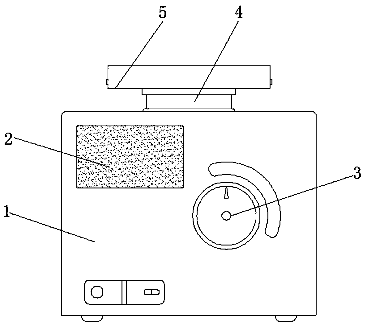
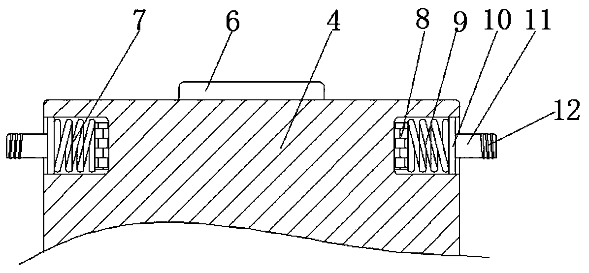
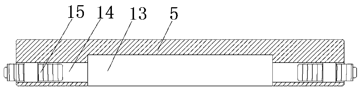
[0019] refer to Figure 1-4 , a mixing device for reagents, comprising a housing 1, the top outer wall of the housing 1 is provided with a rotating shaft 4, and the outer walls on both sides of the rotating shaft 4 are provided with limiting grooves, and the inner walls of the two limiting grooves are provided with limiting mechanisms 7. The top outer wall of the rotating shaft 4 is fixed with a push switch 6 by bolts, and the rotating shaft 4 is clamped with the same rotating head 5 through two limit mechanisms 7. The limit mechanism 7 includes an electromagnet 8, and the electromagnet 8 is fixed by bolts On the inner wall of one side of the limiting groove, the outer


PUM


Abstract

The invention discloses a reagent mixing device. The device includes a shell, a rotating shaft is arranged on the outer wall of the top of the shell, limiting grooves are formed in the outer walls ofthe two sides of the rotating shaft, limiting mechanisms are arranged on the inner walls of the two limiting grooves, a pressing switch is fixed to the outer wall of the top of the rotating shaft through a bolt, the rotating shaft is connected with the same rotating head in a clamped mode through two limiting mechanisms, each limiting mechanism comprises an electromagnet, the electromagnets are fixed to the inner walls of one sides of the limiting grooves through bolts, a spring is fixed to the outer wall of one side of each electromagnet through a bolt, sliding grooves are formed in the innerwalls of the two sides of each limiting groove, and the inner walls of the two sliding grooves are slidably connected with the same sliding plate. By arranging the two limiting mechanisms, the rotating head can be conveniently installed, a threaded pipe on the rotating head is matched with limiting columns on the limiting mechanisms, so the situation that the limiting columns slip off is avoided,and the problem that an existing rotating head is inconvenient to disassemble and replace is solved.

Description


Claims


Application Information

Patent Timeline
Owner 上海联方生物科技有限责任公司
Why Eureka
Try Eureka