Tubing drilling device

A perforating device and tubing technology, which is applied in the direction of production fluid, wellbore/well components, earthwork drilling and production, etc., can solve the problems of tubing strength reduction, perforating gun perforating precision can not be accurately controlled, etc., to achieve precise control of drilling Accuracy, reducing operating costs and construction risks, and improving the success rate of drilling

Active Publication Date: 2020-07-21
PETROCHINA CO LTD
View PDF12 Cites 2 Cited by
  • Summary
  • Abstract
  • Description
  • Claims
  • Application Information

AI Technical Summary

Benefits of technology

This technology allows for precise placement of pipes inside an oil field without causing damage during drillings. By utilizing special tools like wire rods or cords attached to it, these devices are able to create holes within the walls of the borehole while maintaining their stability when placed deeper down hole. These techniques help reduce operational cost and risk compared with traditional methods such as screw-downs or other conventional ways of attaching rigid objects (such as bolts).

Problems solved by technology

The technical problem addressed by this patented technology relates to improving safety during developing high pressure acidic gases (HAG) reservoys or other types of hydrocarbon accumulation from underground sources through tunneling techniques that involve use of special equipment called pipes made up of strong materials like alloys. These tools have limitations when it comes into contact with certain substances found naturally occurring within these environments due to their chemical properties. This limits its effectiveness because they may lose some material overtime causing damage even if only small amounts were left behind after being punched out.

Method used


Image

  • Tubing drilling device
  • Tubing drilling device

Examples


Embodiment Construction

[0051] In order to make the technical solutions and advantages of the present invention clearer, the embodiments of the present invention will be further described in detail below in conjunction with the accompanying drawings.

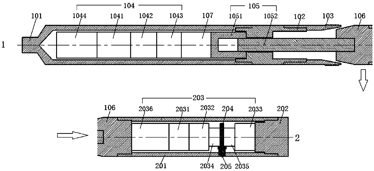
[0052] The embodiment of the present invention provides a oil pipe drilling device, as attached figure 1 As shown, the oil pipe drilling device includes: an anchoring mechanism 1 and a drilling mechanism 2 . Wherein, the anchoring mechanism 1 includes: an upper sleeve 101 connected in sequence from top to bottom, an upper joint 102, a slip 103, an upper driving part 104 located inside the upper sleeve 101, and an upper shaft connected to the upper driving part 104. The moving part 105, the cone 106 connected with the upper driving part 105. Wherein, the upper driving member 104 drives the cone 106 to move up and down through the upper transmission member 105 , so that the cone 106 enters or disengages from the slips 103 . The punching mechanism 2 includ


PUM


Abstract

The invention discloses a tubing drilling device, and relates to the field of oil and gas field development. The tubing drilling device comprises an anchoring mechanism and a drilling mechanism, the anchoring mechanism comprises an upper sleeve, an upper joint and a slip connected sequentially from top to bottom, an upper driving part located in the upper sleeve, an upper transmission part connected with the upper driving part and a cone connected with the upper transmission part, the upper driving part drives the cone to move up and down through the upper transmission part so as to make the cone enter or leave the slip, the drilling mechanism comprises a lower sleeve connected with the cone, a lower joint connected with the lower sleeve, a lower driving part located in the lower sleeve, alower transmission part connected with the lower driving part and a drilling part connected with the lower transmission part, and the lower driving part drives the drilling part to punch a tubing through the lower transmission part. The tubing drilling device can accurately control the drilling accuracy of the tubing and improves the success rate of drilling, the operation cost and construction risk can be reduced, and meanwhile, the integrity of a wellbore can be ensured.

Description


Claims


Application Information

Patent Timeline
Owner PETROCHINA CO LTD
Why Eureka
Try Eureka