Parallel pair cable with continuous characteristic impedance

A characteristic impedance and continuity technology, applied in the direction of insulated cables, twisted/quad-stranded cables, cables, etc., can solve problems such as discontinuity of cable characteristic impedance and influence of cable signal integrity, and achieve To achieve the effect of continuity and integrity

Pending Publication Date: 2021-09-28
深圳九天数通科技有限公司
View PDF0 Cites 0 Cited by
  • Summary
  • Abstract
  • Description
  • Claims
  • Application Information

AI Technical Summary

Problems solved by technology

[0003] The purpose of the present invention is to provide a parallel pair cable whose characteristic impedance can maintain continuity, which solves the problem that the characteristic impedance of the cable is discontinuous. When the signal frequency is higher, the wavelength is shorter, and the characteristic impedance of the cable is discontinuous. Integrity issues with serious implications

Method used


Image

  • Parallel pair cable with continuous characteristic impedance
  • Parallel pair cable with continuous characteristic impedance
  • Parallel pair cable with continuous characteristic impedance

Examples


Example Embodiment

[0024] Example

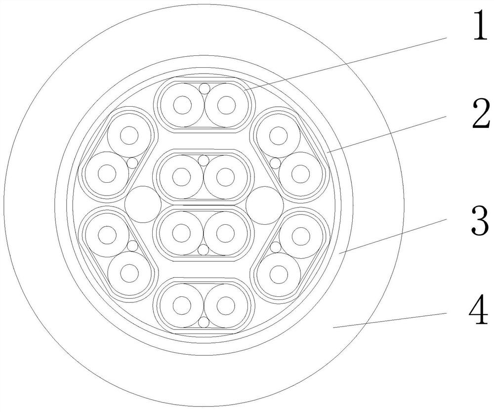
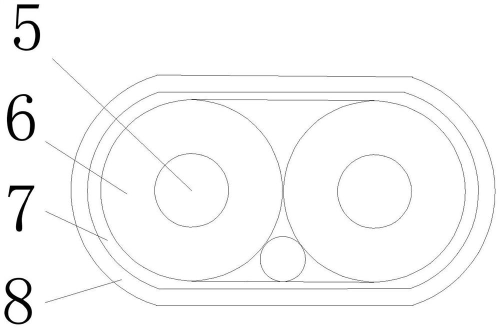
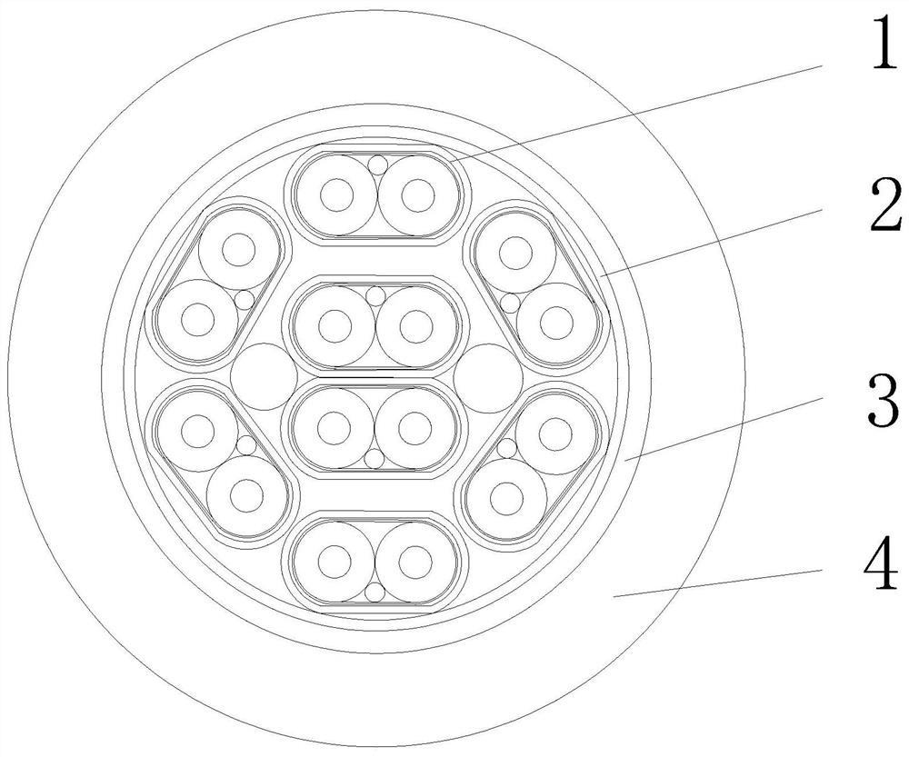
[0025] like figure 1 with figure 2 As shown, a 28AWG (1 / 0.0.32) conductor is used, and the insulating layer 6 is a PE structure as an example.

[0026] When the cable is shielded, the characteristic impedance:

[0027] ε is the dielectric constant of the insulating medium, and a is the outer diameter of the insulating layer 6, and D is the outer diameter of the center conductor 5;

[0028] Known, D = 0.32mm, characteristic impedance = 100 ohms, ε = 2.3;

[0029] The insulating outer diameter A = 1.135 mm is calculated from the above formula to 100 ohms.

[0030] When welding is performed, the third shield layer 7 is removed, and the characteristic impedance of the portion:

[0031] ε is the dielectric constant of the insulating medium, and a is the outer diameter of the insulating layer 6, and D is the outer diameter of the center conductor 5;

[0032] It is known, D = 0.32mm, A = 1.23, ε = 2.6;

[0033] The PCB pad portion (remove the third shield 7 section) c


PUM


Abstract

The invention discloses a parallel pair cable with continuous characteristic impedance and belongs to the technical field of cables. The parallel pair cable comprises a cable core, a first shielding layer, a second shielding layer and a first sheath, wherein the cable core is formed by at least one wire pair, and the first shielding layer, the second shielding layer and the first sheath are sequentially arranged outside the cable core; the wire pair comprises two signal wires, a third shielding layer wrapping the two signal wires and a second sheath arranged on the outer side of the third shielding layer, and each signal wire comprises a central conductor and an insulating layer wrapping the central conductor. The cable is characterized in that the two signal wires are wrapped with a PTFE total insulating layer; The PTFE total insulating layer is located between the third shielding layer and the two signal lines; the cable is provided with the third shielding layer and the PTFE total insulating layer, when the third shielding layer is removed during welding processing and the PTFE total insulating layer is removed at the same time, only the insulating layer is left, it is guaranteed that the characteristic impedance of the cable is the same no matter whether the third shielding layer and the PTFE total insulating layer are removed or not, and therefore the continuity of the characteristic impedance of the cable is achieved, and the integrity of high-frequency communication signals is guaranteed.

Description


Claims


Application Information

Patent Timeline
Owner 深圳九天数通科技有限公司
Why Eureka
Try Eureka