Efficient insulation electric leakage detection circuit and insulation electric leakage detection method
A technology of leakage detection and insulation resistance, which is applied in the field of battery leakage detection system, can solve the problems of high production cost, inaccurate insulation resistance, electric shock, etc., and achieve the effect of low design cost
- Summary
- Abstract
- Description
- Claims
- Application Information
AI Technical Summary
Benefits of technology
Problems solved by technology
Method used
Image

Examples
Embodiment 1
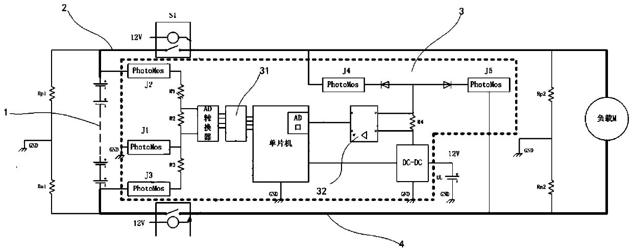
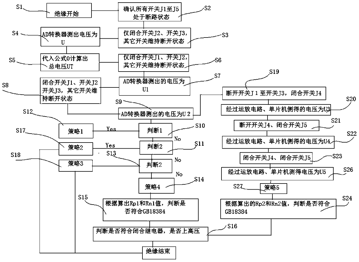
[0093] Such as figure 1 , figure 2 Shown: the insulation leakage detection method adopting the above technical scheme, the specific method is as follows:
[0094] Step S01: Insulation testing starts
[0095] Step S02: Confirm that the switches J1~J5 are all off. At this time, the voltage collected by the A / D conversion module and the internal AD of the microcontroller should be about 0V; if not, it means that the switches J1~J5 cannot guarantee that they are all Completely disconnected, requiring re-inspection and maintenance;
[0096] Step S03: Only close the switch J2 and the switch J3, and keep the other switches in the off state;
[0097] Step S04: At this time, the voltage measured by the A / D conversion module is U; after U is detected, all the switches can be disconnected again according to the situation;
[0098] Step S05: Substitute U into the following formula:
[0099]
[0100] Calculate the total voltage UT;
[0101] Step S06: only switch J1 and switch J2
Embodiment 2
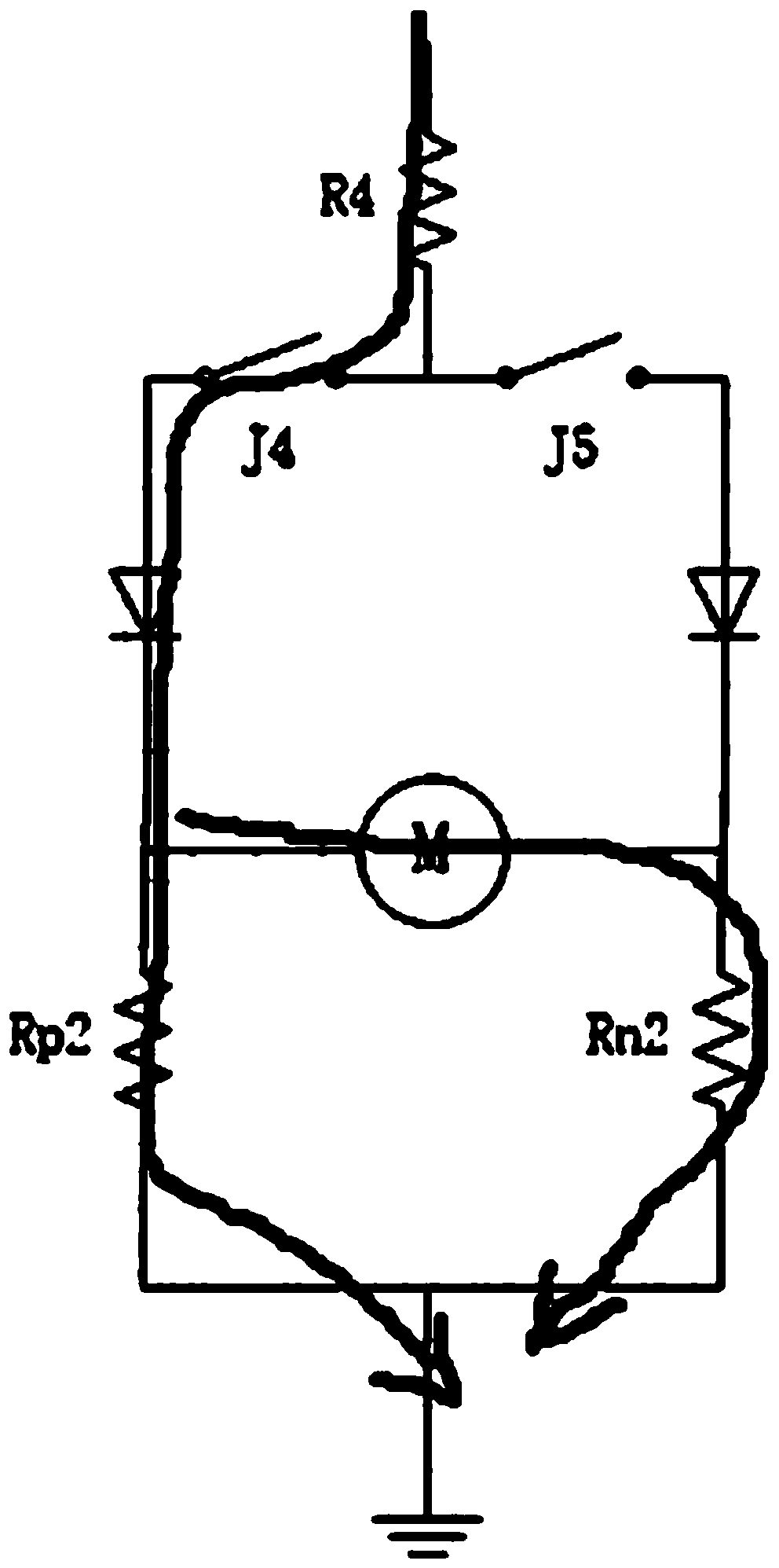
[0119] Step S19: After step S09 is completed, step S09 can start simultaneously with step S10, switch off switches J1-J3, and only close switch J4; jump to step 20;
[0120] Step S20: when the switch J4 is closed, the measured voltage is U3; jump to step S21
[0121] Step S21: Turn off the switches J1~J4, only close the switch J5, and jump to step S22
[0122] Step S22: When only the switch J5 is closed, the measured voltage is U4, and jump to step S23;
[0123] Step S23: Turn off the switches J1~J3, close the switches J4 and J5, and go to step S26
[0124] Step S24: According to the calculated values of Rp2 and Rn2, according to the national standard GB18384, judge whether <100Ω / V or <500Ω / V is satisfied, and if so, jump to step S16
[0125] Step S25: end of insulation;
[0126] Step S26: In step S024, when the values of Rp2 and Rn2 do not satisfy <100 Ω / V or <500 Ω / V, when the switch J4 and switch J5 are closed, the measured voltage is U5, and jump to step S27;
Embodiment 3
[0133] according to figure 1 , figure 2 Shown:
[0134] (1) In the present invention, before the detection of the entire new energy high-voltage system, when J1-J5 is disconnected, the voltages collected by the A / D conversion module and the internal AD of the single-chip microcomputer should be about 0V; if not, it means that the switch J1 ~J5 cannot guarantee that they are completely disconnected, and need to be re-inspected and maintained; this design ensures safety before testing;
[0135] In addition, the inherent insulation resistance Rp1 between the positive bus bar 2 of the battery pack 1 terminal and the shell earth, the inherent insulation resistance Rn1 between the negative bus bar 4 of the battery pack 1 terminal and the shell earth, and the inherent insulation resistance Rp2 between the load terminal positive bus bar 2 and the shell earth , The inherent insulation resistance Rn2 between the total negative busbar 4 at the load end and the earth of the shell; this
PUM
 Abstract
Description
Claims
Application Information
 - R&D Engineer
- R&D Manager
- IP Professional
- Industry Leading Data Capabilities
- Powerful AI technology
- Patent DNA Extraction
Browse by: Latest US Patents, China's latest patents, Technical Efficacy Thesaurus, Application Domain, Technology Topic.
© 2024 PatSnap. All rights reserved.Legal|Privacy policy|Modern Slavery Act Transparency Statement|Sitemap