Pouring system and method for automatic prefabricated T beam

A technology of longitudinal movement and side formwork, applied in the direction of manufacturing tools, mold fixing devices, supply devices, etc., can solve the problems of poor pouring quality of prefabricated light T beams, cumbersome manufacturing process, low production efficiency, etc., and achieves simple and stable structure and operation. Convenient and fast, high production efficiency

Pending Publication Date: 2020-09-25
安徽省路港工程有限责任公司
View PDF0 Cites 3 Cited by
  • Summary
  • Abstract
  • Description
  • Claims
  • Application Information

AI Technical Summary

Benefits of technology

This patented technology allows for efficient and consistently producing customizable tiles or other products that have specific shapes without requiring complex processes like casting them into molds beforehand. It also eliminates complicated steps involved during assembly by allowing the poured material to flow smoothly over multiple templates instead of just one. Overall, this new method provides technical benefits such as improved production speed, reduced defective parts, simplified fabrication procedures, higher accuracy, better distribution capabilities, more precise dimensions, etc., making it suitable for mass market applications.

Problems solved by technology

This patented describes an improvement in making high strength steel tube tubes that are easier and more efficient than traditional casting processes due to their simplified design. However, current methodologies have limitations such as requiring expensive equipment or complex steps during fabrication, leading to lower productivity rates compared to new designs made from simpler materials like plastic foams.

Method used


Image

  • Pouring system and method for automatic prefabricated T beam
  • Pouring system and method for automatic prefabricated T beam
  • Pouring system and method for automatic prefabricated T beam

Examples


Embodiment Construction

[0049] In order to make the purpose, technical solutions and advantages of the embodiments of the present invention clearer, the technical solutions in the embodiments of the present invention will be clearly and completely described below in conjunction with the embodiments of the present invention. Obviously, the described embodiments are part of the present invention Examples, not all examples. Based on the embodiments of the present invention, all other embodiments obtained by persons of ordinary skill in the art without creative efforts fall within the protection scope of the present invention.

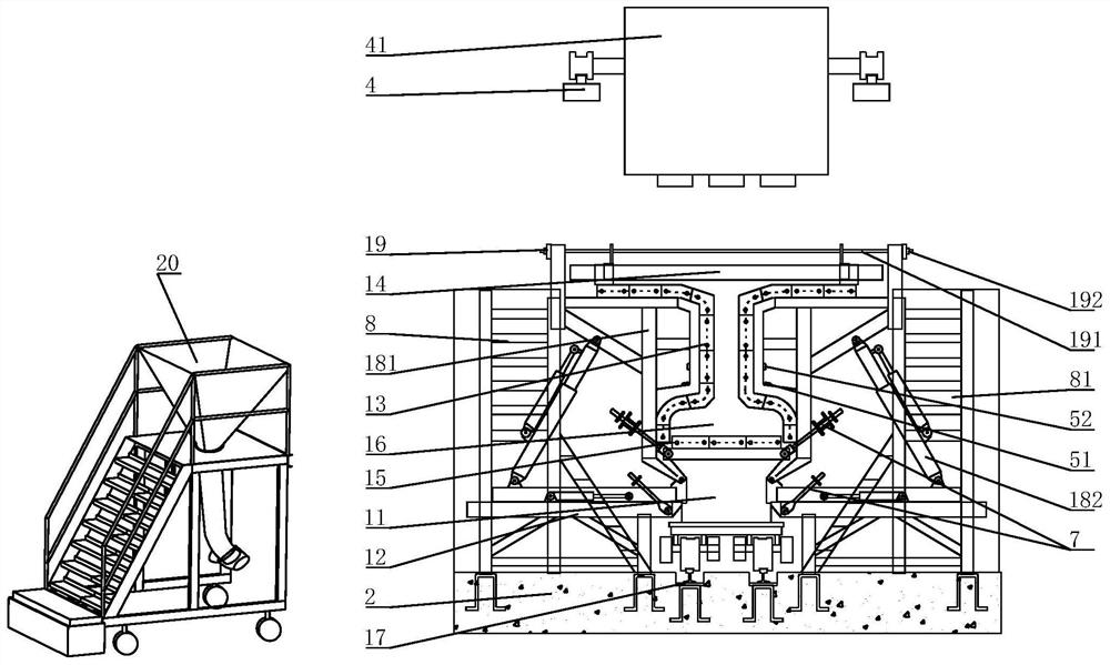
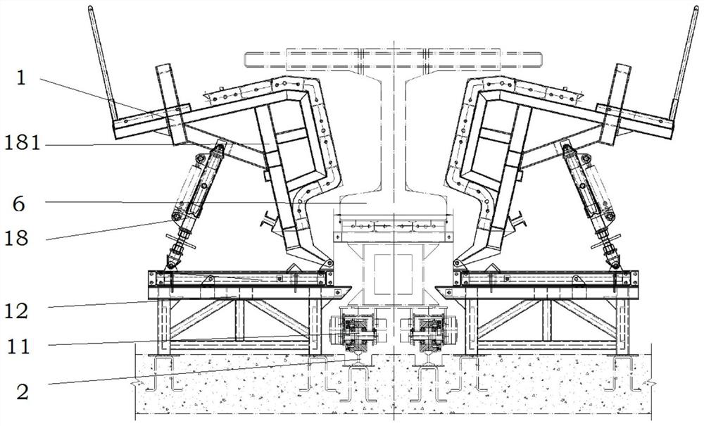
[0050] combined with Figure 1 to Figure 11 , The present invention provides a pouring system and pouring method for an automated prefabricated T-beam, aiming at improving the production efficiency and product quality of the automated prefabricated T-beam.

[0051] Specifically, an automated prefabricated T-beam pouring system includes a steel form system 1, a pouring platform 2, a


PUM


Abstract

The invention provides a pouring system and method for an automatic prefabricated T beam. A bottom formwork is arranged on an upper end platform of a longitudinal moving trolley of a steel formwork system, end formwork are arranged at the two longitudinal ends of the longitudinal moving trolley; the horizontal trusses are arranged on the two sides of a longitudinal moving rail of the longitudinalmoving trolley, horizontal trusses are arranged on the two sides of a longitudinal moving rail of the longitudinal moving trolley, side formworks are arranged on the horizontal trusses of a pouring pedestal, the lower ends of the side formworks are rotationally connected with the horizontal trusses and are in butt joint to form a pouring containing cavity of the prefabricated light T beam, the size of a steel reinforcement framework is matched with that of the pouring containing cavity, a feeding hole of a distributing machine of a distributing system is arranged in a mode of corresponding toa torpedo ladle, and vibrators are arranged on the outer walls of the side formworks. According to the pouring system and method, through positioning combination of the bottom formwork, the end formworks, the side formworks and the upper formwork, shaping and pouring machining of the prefabricated light T beam are achieved, and the structure is simple and stable; the torpedo ladle and the distributing machine are fully automatically controlled, and the distributing machine automatically distributes materials according to the pouring thickness of each layer, so that the production efficiency and the production quality are greatly improved.

Description


Claims


Application Information

Patent Timeline
Owner 安徽省路港工程有限责任公司
Why Eureka
Try Eureka