Method and system for transmitting vehicle video picture data based on 5G, and storage medium
A video data and vehicle technology, applied in the field of 5G video processing, can solve problems such as high wiring costs, audio and video delays, and stuck pictures
- Summary
- Abstract
- Description
- Claims
- Application Information
AI Technical Summary
Problems solved by technology
Method used
Image

Examples
Embodiment 1
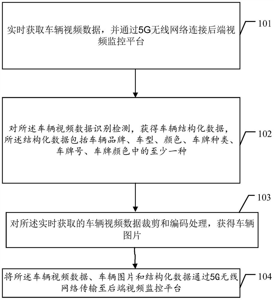
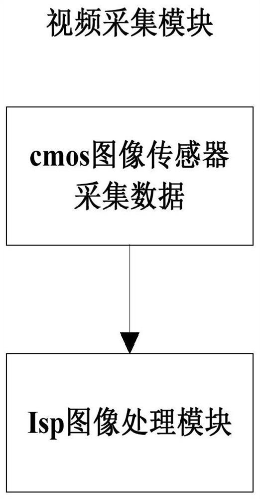
[0031] see figure 2 , collect the raw video data of the vehicle captured in the field of view from the image sensor, and after image processing by the isp module, output the yuv video frame data yuv_i at the time stamp tv_i.
[0032] Acquisition method: After the natural light signal of the vehicle captured in the field of view is projected to the photosensitive area of the image sensor through the lens, the image sensor undergoes photoelectric conversion and sends the original image in Bayer format to the video acquisition module isp module.
[0033] Step 102, identifying and detecting the real-time acquired vehicle video data to obtain vehicle structured data, the structured data including at least one of vehicle brand, model, color, license plate type, license plate number, and license plate color;
[0034] Further, see Figure 4 , 5 Before identifying and detecting the vehicle video data acquired in real time, an alarm step is included: judging whether there is a vehicle
Embodiment 2
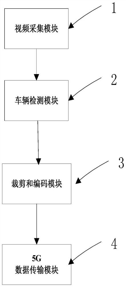
[0036] see Figure 5 , 4 :
[0037] 1. The original video of the vehicle captured in the field of view is input to the video acquisition module in YUV format data frames.
[0038] 2. The vehicle video acquisition module unit is responsible for analyzing each frame of YUV raw data generated by the camera, and outputting alarm information event_n_i, such as including the ID of vehicle A (each vehicle has a unique number), time stamp T, position [starting point (1500, 500), end point (1700,640)], structured data structDat_u (including vehicle brand, model, color, license plate type, license plate number, license plate color).
[0039] 3. Cache the alarm event event_n_i to the event list event_list.
[0040] Example of the alarm collection process of the vehicle video collection module:
[0041] Vehicle A is captured in the field of view of the image sensor, and the video acquisition module senses and collects the video of vehicle A, triggers an alarm event, and obtains structure
Embodiment 3
[0044] see image 3 ,4
[0045] 1. The cropping and encoding module first encodes the original yuv video frame yuv_i at a certain time T1 to generate videoJpg_i through the vehicle position information,
[0046] 2. Then at a certain moment T is located at the coordinate position [start point (1500, 500), end point (1700, 640)], cut out the vehicle picture vehPicYuv_u from the complete video frame picture yuv_u, and the video encoding module encodes and generates vehicle A in Vehicle picture vehPicJpg_u under T2 at a certain moment.
[0047]An example can be used here to illustrate the understanding. The cropping coding module clips the coding process through the vehicle position information. There may be multiple vehicles appearing in the video, in multiple lane positions, such as marked as [starting point (1500, 500), ending point (1700, 640) Vehicle A at ], and vehicle B at other places, T1 will encode the original yuv video frame yuv_i at a certain time to generate a video f
PUM
 Abstract
Description
Claims
Application Information
 - R&D Engineer
- R&D Manager
- IP Professional
- Industry Leading Data Capabilities
- Powerful AI technology
- Patent DNA Extraction
Browse by: Latest US Patents, China's latest patents, Technical Efficacy Thesaurus, Application Domain, Technology Topic.
© 2024 PatSnap. All rights reserved.Legal|Privacy policy|Modern Slavery Act Transparency Statement|Sitemap