Novel laser cladding device

A new type of laser cladding technology, applied in mixers with rotating stirring devices, transportation and packaging, mixers, etc., can solve the problems of inconvenient stirring, inconvenient liquid materials, inconvenient fixing of steel pipes of different sizes, etc. Achieve the effect of improving work efficiency and reducing workload

Pending Publication Date: 2020-12-04
苏州华意铭铄激光科技有限公司
View PDF5 Cites 0 Cited by
  • Summary
  • Abstract
  • Description
  • Claims
  • Application Information

AI Technical Summary

Problems solved by technology

[0005] The technical problem to be solved by the present invention is to provide a new type of laser cladding device to solve the inconvenience of fixing steel pipes of differen

Method used


Image

  • Novel laser cladding device
  • Novel laser cladding device
  • Novel laser cladding device

Examples


Example Embodiment

[0027] The present invention will be described in detail in conjunction with the accompanying drawings:

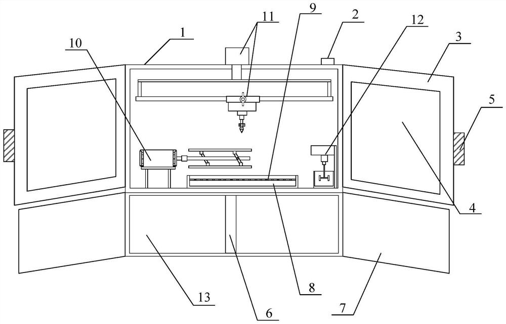
[0028] Append figure 1 Attach figure 2 Shown, a novel laser cladding apparatus according to the present invention, comprises a mounting housing 1, a switch 2, door 3, the observation window 4, a handle 5, a separator 6, the shield plate 7, a collecting box 8, the filter 9, the adjustable mounting structure 10 rotating machine, self-adjusting movable structure cladding machine 11, and motor 12 is disposed stirred tank frame structure 13, the switch 2 is screwed to the right side of the housing 1 of the mounting surface; the said door is provided with two 3, the door panel 3 are respectively connected to the left and right sides of the hinge housing 1 is mounted; the viewing window 4 embedded in the intermediate position of the door panel 3; screw connection of the handle 5 3 in the intermediate position outside of the door panel; said spacer screw 6 connected to an intermediate ve


PUM


Abstract

The invention discloses a novel laser cladding device. The novel laser cladding device comprises a mounting box body, a switch, door plates, observation windows, handles, a partition plate, protectiveplates, a collecting box, a filter screen, an adjustable mounting rotating machine structure, a movable self-adjusting cladding machine structure, a motor stirring frame structure and a placement box, and the switch is connected to the right side of the upper surface of the mounting box body through screws; the two door plates are connected to the left side and the right side of the mounting boxbody through hinges separately; the observation windows are embedded in the middle positions of the interiors of the door plates; the handles are connected to the middle positions of the outer sides of the door plates through screws; and the partition plate is vertically connected to the middle of the interior of the placement box through screws. Through the arrangement of supporting rods, a mounting plate, a rotating motor, a fixed rod, folding frames, supporting plates and adjusting bolts, steel pipes of different sizes can be mounted at the upper part of the novel laser cladding device, anda user can perform laser cladding work on the steel pipes of different sizes more conveniently.

Description


Claims


Application Information

Patent Timeline
Owner 苏州华意铭铄激光科技有限公司
Why Eureka
Try Eureka