Construction steel bar machining device

A processing device and a technology for building steel bars, which are applied in the field of construction engineering, can solve problems such as unloading of steel bars, collision of steel bars, damage of steel bars, etc., achieve fast and convenient automatic unloading operations, and avoid damage to steel bars

Active Publication Date: 2020-12-08
安徽金贺财建筑工程有限公司
View PDF11 Cites 0 Cited by
  • Summary
  • Abstract
  • Description
  • Claims
  • Application Information

AI Technical Summary

Benefits of technology

This technology allows for efficient use of space by allowing an electric machine (power motor) to work more efficiently without being obstructive or damaging other parts that it'll be installed next. It uses specialized components like brackets made up of wires attached between them, rods connected to slides, rails mounted under tensioners, wheels placed above the reinforceings, and chucks used to hold fixtures during construction operations. By adjusting certain parameters such as length, diameter, and spacing of these components, there can also perform various functions related to improving efficiency while minimizing interference caused by external factors like vibrational waves transmitted throughout the structure. Overall, this innovation makes building structures faster and easier than traditional methods due to its improved performance and ease of assembly process compared to existing systems.

Problems solved by technology

The technical problem addressed by this patented technology relates to how to safely remove heavyweight steel planks from building constructions during manufacturing without causing harm or injury caused by collision with other objects such as iron rails that might also fall on them when they shouldn't.

Method used


Image

  • Construction steel bar machining device
  • Construction steel bar machining device
  • Construction steel bar machining device

Examples


Embodiment approach

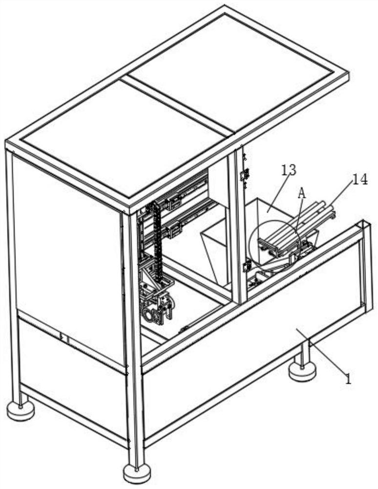
[0033] As an embodiment of the present invention, the placement frame 20 includes a bottom plate and two sloping plates, and the top sides of the two sloping plates are installed on the top side of the bottom plate at 135°, and wheels are installed at the bottom of the bottom plate and on both sides of the discharge chute 24. seat, and rollers are installed in the wheel seat, the limiter 16 includes a horizontal plate and a lifting plate, and the bottom side of the lifting plate and the bottom side of the horizontal plate are 150°, the horizontal plate is connected with the inner wall of the frame 1, and the rollers of the wheel seat are located on the horizontal plate On the top side, the placing frame 20 is in a horizontal state, and the working elongation of the second air pressure rod 15 drives the translation frame 19 to slide on the second slide rail 21. At this time, the rollers move along the limiter 16. Frame 20 rotates on rotating shaft 17 by bearing seat 18, and this mo


PUM


Abstract

The invention discloses a construction steel bar machining device which comprises a frame. A transverse frame is horizontally mounted at one end of the inner part of the frame, a sliding frame is slidably mounted on the outer side of the transverse frame, a sliding seat is slidably mounted on the outer side of the sliding frame, a mounting frame is mounted on the outer side of the sliding seat, and a first pneumatic pressure rod is horizontally mounted at the bottom of the mounting frame. The second pneumatic pressure rod works and extends to drive a translation frame to slide on a second sliding rail, at the moment, a roller moves along a limiting piece, when the roller moves to a lifting plate, a placing frame rotates on a rotating shaft through a bearing seat, at the moment, one end ofa steel bar penetrates through a discharging groove to be in contact with the top side of the lifting plate and continuously moves along with the placing frame, the steel bar extends out continuouslyfrom the inner part of the discharging groove, when the placing frame moves to the bottom end of the limiting piece, the steel bar automatically falls into a hopper, at the moment, the second pneumatic pressure rod contracts to return to the original position, the automatic discharging operation of the steel bar is rapidly and conveniently completed, and the condition that the steel bar is damageddue to direct discharging is avoided.

Description


Claims


Application Information

Patent Timeline
Owner 安徽金贺财建筑工程有限公司
Why Eureka
Try Eureka