Atomization device

An atomization device and atomizer technology, applied in the direction of tobacco, etc., can solve problems such as excessive temperature and harmful substances, insufficient delivery of smoke liquid, incomplete atomization, etc., and achieve the effect of easy adjustment and control, and avoiding adverse effects

Pending Publication Date: 2020-12-25
SHENZHEN SUNLORD ELECTRONICS
View PDF6 Cites 0 Cited by
  • Summary
  • Abstract
  • Description
  • Claims
  • Application Information

AI Technical Summary

Benefits of technology

This patented device uses an absorbent material for liquids like gasoline (liquified fuel). When there are no more flammable substances than usual, they tend to stay inside rather than moving around within their own container. However, if one part becomes too hot while another gets cold enough, condensation occurs at both ends causing them to stick together easily. To solve these problems, the device includes a mechanism called a switch system that opens upon use but closes tightly after usage. By doing this, the smoking machine's energy consumption decreases without affecting its performance. Additionally, the design allows for precise regulation over how much liquid remains behind before being returned back up again. Overall, this technology improves safety measures against fires and reduces environmental pollution associated with combustion processes.

Problems solved by technology

This patented describes an electronic cigarettes device where different parts inside can get wet when they come into contact due to their hydrophilicity. To solve these issues, certain fibers have been developed that allow them to absorb more water than other ones while still allowing oils from one type of fluid to pass therethrough without getting stuck up. However, even if some fibers were designed properly, too much moisture could lead to fires caused by overheating and decompositing harmful compounds produced during combustion. Additionally, current methods require constant maintenance because the oil supply cannot change frequently leading to leaks between sections of the apparatus.

Method used


Image

  • Atomization device

Examples


Embodiment Construction

[0022] Embodiments of the present invention will be described in detail below. It should be emphasized that the following description is only exemplary and not intended to limit the scope of the invention and its application.

[0023] It should be noted that when an element is referred to as being “fixed” or “disposed on” another element, it may be directly on the other element or be indirectly on the other element. When an element is referred to as being "connected to" another element, it can be directly connected to the other element or indirectly connected to the other element. In addition, the connection can be used for fixation as well as for coupling or communication.

[0024] It is to be understood that the terms "length", "width", "top", "bottom", "front", "rear", "left", "right", "vertical", "horizontal", "top" , "bottom", "inner", "outer" and other indicated orientations or positional relationships are based on the orientations or positional relationships shown in the


PUM


Abstract

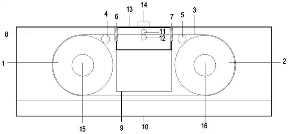
The invention relates an atomization device, which comprises an oil bin, an atomizer and a circulating moving liquid suction mechanism, cigarette liquid is stored in the oil bin, a heating device is arranged in the atomizer, the circulating moving liquid suction mechanism comprises a driving structure and a liquid suction piece coupled with the driving structure, the driving structure is used fordriving the liquid suction piece to move, wherein a moving path of the liquid absorbing piece circularly passes through the heating ranges of the oil bin and the heating device, the liquid absorbing piece absorbs tobacco liquid at the oil bin, and the absorbed tobacco liquid is brought to the heating device by virtue of the movement of the liquid absorbing piece to be heated and atomized; whereinthe moving path of the liquid absorbing part is arranged in a two-dimensional plane or a three-dimensional moving path. According to the atomization device, the amount of tobacco juice conveyed to theheating device can be adjusted and controlled more easily, and therefore adverse effects caused by excessive or insufficient conveying of the tobacco juice are avoided.

Description


Claims


Application Information

Patent Timeline
Owner SHENZHEN SUNLORD ELECTRONICS
Why Eureka
Try Eureka