Cutting fluid regeneration device

A regeneration device and cutting fluid technology, which is applied in liquid separation, grease/oily substance/floating matter removal device, biological water/sewage treatment, etc., can solve the problem of large consumption, short service life of cutting fluid, heavy odor at the production site, etc. problems, to achieve the effects of reducing emissions, saving waste liquid disposal costs, and reducing defective and scrap rates

Pending Publication Date: 2021-01-05
常永青
View PDF5 Cites 0 Cited by
  • Summary
  • Abstract
  • Description
  • Claims
  • Application Information

AI Technical Summary

Benefits of technology

This technology allows for flexible control over how much cutter fluids used during machining work should go through before being returned into circulating systems or disposed off-site. It also includes different types of filters made from various materials designed specifically target specific pollutants such as organics, which helps them stick out faster by absorbing it more effectively than other liquids like water without causing damage on equipment. Overall, this technology reduces environmental concerns associated with excessively large amounts of spent cutting fluid while improving efficiency and reducing costly treatments downstream.

Problems solved by technology

The technical problem addressed in this patented solution involves improving the efficiency with which cut fluids are recovered during metal processing machines that use them or disposal thereof while reducing harmful emissions such as bad smells caused by excessive handling.

Method used


Image

  • Cutting fluid regeneration device
  • Cutting fluid regeneration device

Examples


Embodiment Construction

[0022] In order to make the technical solutions of the present invention clearer and clearer to those skilled in the art, the present invention will be further described in detail below in conjunction with the embodiments and accompanying drawings.

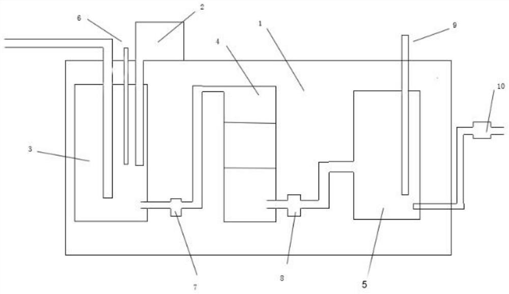
[0023] figure 1 A preferred implementation form of the cutting fluid device is shown, including a regeneration tank 1 and a floating oil recovery device 2 . The floating oil recovery device 2 is located at the upper end of the regeneration box 1 outside. The regeneration tank 1 is provided with a settling tank 3 , a separation tank 4 and a liquid storage tank 5 sequentially from left to right. The upper part of the settling tank 3 is connected with the floating oil recovery device 2 , the inlet end of the settling tank 3 is connected with the sewage pipe, and the outlet end of the settling tank 3 is connected with the inlet end of the separation tank 4 through the first self-priming pump 7 . The outlet end of the separation tank 4


PUM


Abstract

The technical problem to be solved by the invention is to provide a cutting fluid regeneration device. The cutting fluid regeneration device comprises a regeneration box body and a floating oil recovery apparatus. The floating oil recovery apparatus is positioned at the upper end outside the regeneration box body. And a settling tank, a separation tank and a liquid storage tank are sequentially arranged in the regeneration box body from left to right. The upper part of the settling tank is communicated with a floating oil recovery apparatus, the inlet end of the settling tank is communicated with a sewage pipe, and the outlet end of the settling tank is communicated with the inlet end of the separation tank through a first self-priming pump. The outlet end of the separation tank is communicated with the inlet end of the liquid storage tank through a second self-priming pump, the outlet end of the liquid storage tank is communicated with a water outlet pipe, the water outlet pipe is provided with a flow regulator, and liquid output from the outlet end of the liquid storage tank is cutting fluid which can be used after regeneration. The filtering precision can be flexibly adjusted according to actual needs, solid particles and miscellaneous oil of the cutting fluid can be rapidly removed, and the cutting fluid can be recycled. The consumption of the cutting fluid is fundamentallyreduced; cutting fluid discharge is reduced; the waste liquid disposal cost is saved; and the defective rate and rejection rate are reduced.

Description


Claims


Application Information

Patent Timeline
Owner 常永青
Why Eureka
Try Eureka