Capping machine

A technology of capping machine and rack, which is applied to conveyors, conveyor objects, flanged bottle caps, etc., can solve the problems of time-consuming and laborious operation, manual installation, low work efficiency, etc., to avoid manual operation and facilitate pressing. The effect of tightly sealing the cover and improving work efficiency

Inactive Publication Date: 2021-01-22
苏州仁宇机械有限公司
View PDF7 Cites 1 Cited by
  • Summary
  • Abstract
  • Description
  • Claims
  • Application Information

AI Technical Summary

Benefits of technology

This technology helps prevent accidental opening or damaging of an existing lid used during filling processes when drink containers have caps that move around inside them. It also ensures better pressure between the cup body's top surface and its bottom surfaces while keeping it secure from external impacts. Additionally, this design prevents excessive force applied through hands-free methods like squeezing out liquids without causing any harm if they shouldn’ve been done incorrectly. Overall, these technical benefits improve safety measures and enhance working efficacy.

Problems solved by technology

The technical problem addressed in this patented method relates to improving the security of beer bottled packages during transportation from manufacturing facilities to retail stores where consumers purchase them without opening their capes before consumption. Current manual installations require significant human effort, slow down production rates, and may lead to errors that could harm healthcare workers who handle these products.

Method used


Image

  • Capping machine
  • Capping machine
  • Capping machine

Examples


Embodiment

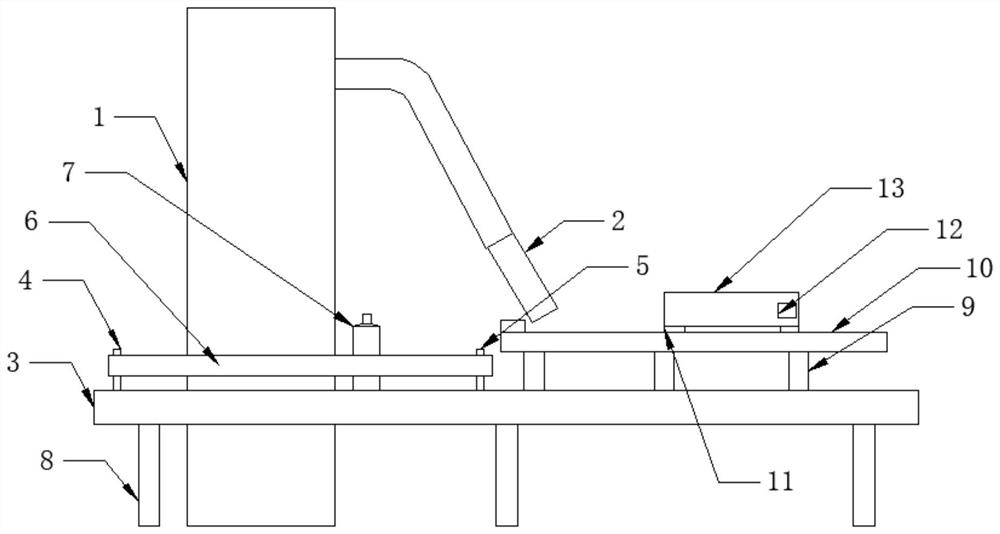
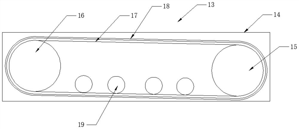
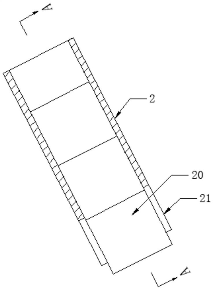
[0025] see Figure 1-4 , the present invention provides a technical solution: a capping machine, including a frame 3, a conveyor belt is installed in the middle of the frame 3, the conveyor belt is driven by a first motor, and support feet are fixedly connected to the bottom of the frame 3 8. Clamping devices are provided on the front and rear sides above the frame 3, the clamping devices include a pressure belt 6, a driving roller 4 and a driven roller 5, and the driving roller 4 is installed on the left side above the frame 3 , the driving roller 4 is rotationally connected with the frame 3, and the driving roller 4 is driven by a second motor, the driven roller 5 is installed on the right side above the frame 3, and the driven roller 5 and the frame 3 Rotationally connected, a pressure belt 6 is installed between the driving roller 4 and the driven roller 5, and the second motor drives the driving roller 4 to rotate so that the pressure belt 6 moves, and the pressure belts 6 o


PUM


Abstract

The invention belongs to the technical field of plastic bottle capping, and particularly relates to a capping machine which comprises a rack. A conveyor belt is installed in the middle of the rack anddriven by a first motor, supporting legs are fixedly connected to the bottom of the rack, clamping devices are arranged on the front side and the rear side of the upper portion of the rack, each of the clamping devices comprises a pressing belt, a driving roller and a driven roller, the driving roller is installed on the left side of the upper portion of the rack, the driving roller is rotatablyconnected with the rack, the driving roller is driven by a second motor, the driven roller is installed on the right side of the upper portion of the rack, the pressing belt is installed between the driving roller and the driven roller, and the pressing belts on the front side and the rear side are parallel to each other. Beverage bottles are conveyed through the conveyor belt, when the beverage bottles pass through a feeding head, bottle caps of the beverage bottles are clamped into sealing caps, in the continuous moving process of the beverage bottles, springs are compressed, and the distance between the tail ends of the baffles on the front side and the rear side is increased, so that the sealing caps are pulled out and arranged on the beverage bottles in a sleeving mode.

Description


Claims


Application Information

Patent Timeline
Owner 苏州仁宇机械有限公司
Why Eureka
Try Eureka