Alignment method of photoetching process
A technology of photolithography and alignment marking, which is applied in the field of photolithography, can solve the problems that alignment cannot be directly monitored, increase the instability of overlay performance and the complexity of online control, etc., so as to improve the accuracy and stability of overlay, The effect of reducing process cost and low process requirements
- Summary
- Abstract
- Description
- Claims
- Application Information
AI Technical Summary
Benefits of technology
Problems solved by technology
Method used
Image

Examples
Embodiment 1
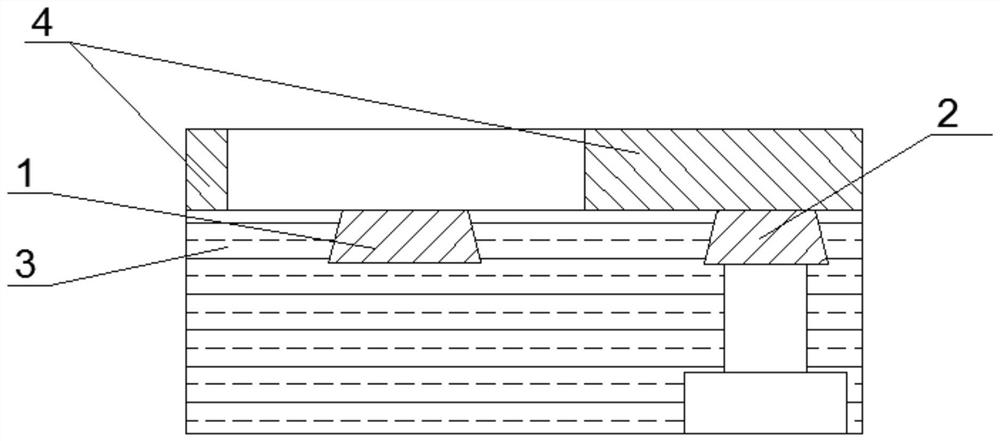
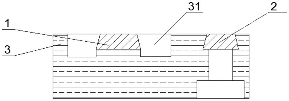
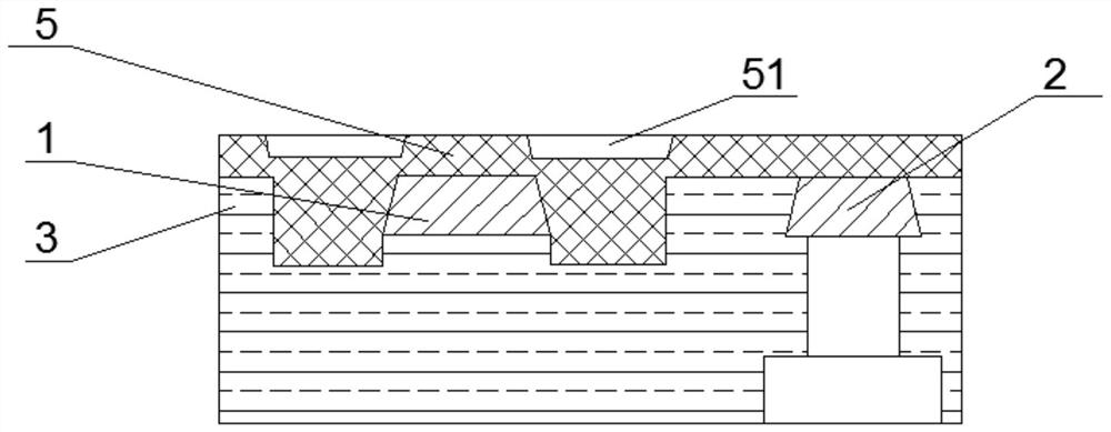
[0028] An embodiment of the present invention provides an alignment method for a photolithography process, such as Figure 1-5 shown, including:
[0029] S1, providing the first functional graphic 2, the alignment mark 1 and the filling medium 3 used to fill the gap between the first functional graphic and the alignment mark, the first functional graphic 2, the alignment mark 1 and the filling medium 3 the upper surfaces are all in the first plane;
[0030] In the above step S1, the following steps are further included:
[0031] S11: providing a substrate, forming a first functional layer on the substrate;
[0032] In this embodiment, the first functional layer is the bottom electrode layer;
[0033] S12: coating photoresist on the first functional layer;
[0034] S13: Expose and develop the photoresist by using the first mask having patterns corresponding to the alignment mark 1 and the first functional pattern 2, and form a pattern corresponding to the alignment mark 1 and
Embodiment 2
[0068] This embodiment provides an alignment method of a photolithography process, which is described by taking the photolithography process of the top electrode of a magnetic random access memory as an example, including:
[0069] S1, providing a base, the base includes a substrate and a first functional pattern formed on the substrate, an alignment mark and a filling medium, and the upper surfaces of the first functional pattern, the alignment mark and the filling medium are all on the second within a plane;
[0070] Above-mentioned S1 step further comprises the following steps:
[0071] S11: providing a substrate, forming a first functional layer on the substrate;
[0072] In this embodiment, the substrate is a bottom electrode pattern and a supporting device for supporting the bottom electrode. In this embodiment, the first functional layer is the magnetic tunnel junction layer.
[0073] S12: coating photoresist on the first functional layer;
[0074] S13: exposing and de
Embodiment 3
[0108] An embodiment of the present invention provides an alignment method for a photolithography process, including:
[0109] S1, providing a base, the base includes a substrate and a first functional pattern formed on the substrate, an alignment mark and a filling medium, and the upper surfaces of the first functional pattern, the alignment mark and the filling medium are all on the second within a plane;
[0110] Above-mentioned S1 step further comprises the following steps:
[0111] S11: providing a substrate, and coating photoresist on the substrate;
[0112] S12: exposing and developing the photoresist by using the first mask with the alignment mark and the first functional pattern, and removing the photoresist at the alignment mark and the first functional pattern;
[0113] In this embodiment, the exposure method can be selected from contact exposure, proximity exposure or projection exposure.
[0114] In this embodiment, the first functional pattern is the bottom elect
PUM
 Abstract
Description
Claims
Application Information
 - R&D Engineer
- R&D Manager
- IP Professional
- Industry Leading Data Capabilities
- Powerful AI technology
- Patent DNA Extraction
Browse by: Latest US Patents, China's latest patents, Technical Efficacy Thesaurus, Application Domain, Technology Topic.
© 2024 PatSnap. All rights reserved.Legal|Privacy policy|Modern Slavery Act Transparency Statement|Sitemap