High-temperature bending fatigue in-situ test device and method

A technology of bending fatigue and in-situ testing, applied in the direction of measuring devices, using stable bending force to test the strength of materials, instruments, etc.

Pending Publication Date: 2021-03-16
JILIN UNIV
View PDF0 Cites 1 Cited by
  • Summary
  • Abstract
  • Description
  • Claims
  • Application Information

AI Technical Summary

Problems solved by technology

[0004] The purpose of the present invention is to provide a high-temperature bending fatigue in-situ test device and method, which solves the above-mentioned

Method used


Image

  • High-temperature bending fatigue in-situ test device and method
  • High-temperature bending fatigue in-situ test device and method
  • High-temperature bending fatigue in-situ test device and method

Examples


Embodiment Construction

[0045] The detailed content of the present invention and its specific implementation will be further described below in conjunction with the accompanying drawings.

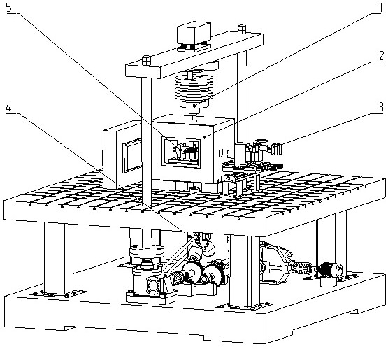
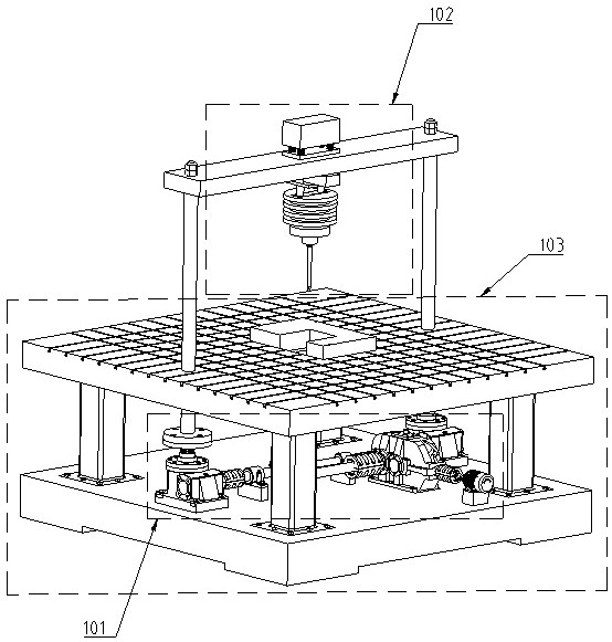
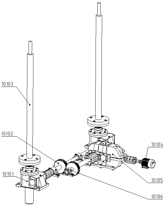
[0046] see Figure 1 to Figure 20 As shown, the high-temperature bending fatigue in-situ testing device and method of the present invention, the device is composed of an electromagnetic resonance loading module, a hydraulic loading module, a high-temperature loading module, an in-situ monitoring module, and a sample clamping device. Among them, the electromagnetic resonance loading module can realize the high frequency bending fatigue loading of the tested material sample; the hydraulic loading module can realize the low frequency bending fatigue loading of the tested material sample; the high temperature loading module can realize the high temperature and variable temperature of the tested material sample Environmental loading; the in-situ monitoring module can monitor the characteristics and mechanism of crack init


PUM


Abstract

The invention relates to a high-temperature bending fatigue in-situ test device and method. The device is composed of an electromagnetic resonance loading module, a hydraulic loading module, a high-temperature loading module, an in-situ monitoring module and a sample clamping device. The electromagnetic resonance loading module can realize high-frequency bending fatigue loading of a tested sample;the hydraulic loading module can realize low-frequency bending fatigue loading of the tested sample; the high-temperature loading module can realize loading of a tested sample in high-temperature andvariable-temperature environments; the in-situ monitoring module can monitor the characteristics and mechanisms of crack initiation and propagation of the sample; and the sample clamping device can realize firm clamping and accurate positioning of tested samples with different sizes and different shapes. The device and the method can be used for high-resolution in-situ test of high-temperature bending fatigue performance, and provide a feasible technical means for material bending fatigue performance test and service safety guarantee in the fields of aerospace, automobile manufacturing, railtransit and the like.

Description


Claims


Application Information

Patent Timeline
Owner JILIN UNIV
Why Eureka
Try Eureka