Dielectric constant measuring jig and method based on parallel plate capacitance method

A dielectric constant and jig technology, applied in the measurement of electrical variables, measuring devices, measuring resistance/reactance/impedance, etc., can solve the needs of measurement samples that cannot meet various sizes, the error of the measured capacitance value, the dielectric constant Insufficient accuracy and other problems, to achieve the effect of good parallelism, reduced impact and low cost

Active Publication Date: 2021-03-23
HUAZHONG UNIV OF SCI & TECH
View PDF15 Cites 2 Cited by
  • Summary
  • Abstract
  • Description
  • Claims
  • Application Information

AI Technical Summary

Benefits of technology

This patented technology describes a new way to measure material properties called conductivity or permittivity that involves comparing different materials at specific temperatures. By doing this it provides valuable insights into how these materials behave differently under certain conditions. It also includes various methods such as measurements involving parallel-plate capacitive (PC), inductive/resistive (RF)/dieletronics (DRC). These technologies have been developed over time due to their high precision and efficiency during experimentation processes. Overall, they provide useful tools for studying complex physical systems like biological tissue.

Problems solved by technology

The technical problem addressed in this patents relating to accurate measurements of dielectrics with different dimensions involves accurately determining specific values called permittivity (perm) based upon certain characteristics like thicknesses, orientation, etc., without requiring complicated calculations involving multiple testers' limitations.

Method used


Image

  • Dielectric constant measuring jig and method based on parallel plate capacitance method
  • Dielectric constant measuring jig and method based on parallel plate capacitance method
  • Dielectric constant measuring jig and method based on parallel plate capacitance method

Examples


Embodiment Construction

[0040] In order to make the object, technical solution and advantages of the present invention clearer, the present invention will be further described in detail below in conjunction with the accompanying drawings and embodiments. It should be understood that the specific embodiments described here are only used to explain the present invention, not to limit the present invention.

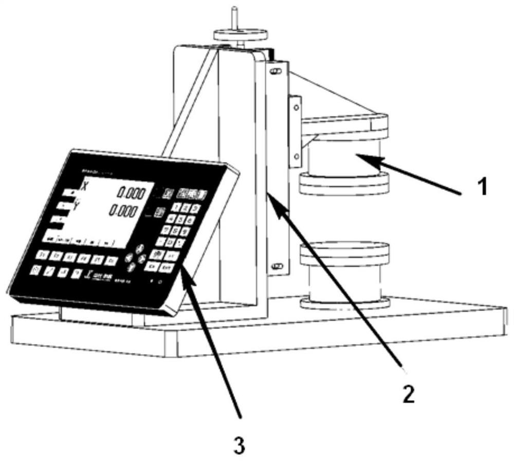
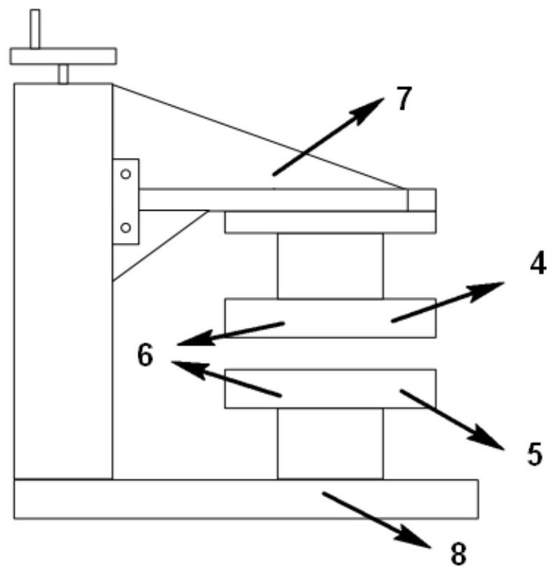
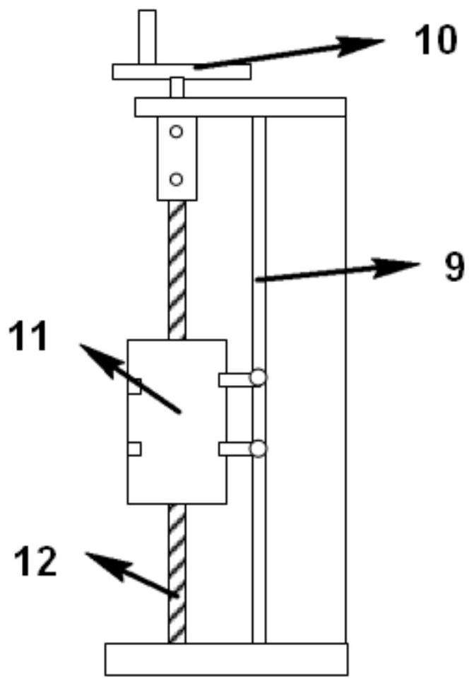
[0041] The invention provides a dielectric constant measurement fixture based on the parallel plate capacitance method, comprising: an electrode system, a carriage system, a thickness measurement system and a base plate, used to follow an impedance analyzer (such as the IM3570 of Hioki Corporation (HIOKI)) Cooperate with detecting the capacitance value of the sample, and obtain the dielectric constant of the sample.

[0042] The electrode system is used to form a parallel plate capacitor with the sample to be tested, so that the dielectric constant of the sample is calculated according to the measured


PUM


Abstract

The invention discloses a dielectric constant measuring jig and method based on a parallel plate capacitance method, and belongs to the technical field of material measurement application. The measuring jig comprises an electrode system, a sliding frame system, a thickness measuring system and a base plate. The electrode system comprises an upper pole plate, a lower pole plate, a supporting columnand a triangular bracket. The sliding frame system comprises a rotating hand wheel, a ball screw, a sliding rail and a sliding block, the rotating hand wheel is connected with the ball screw, the sliding block moves on the sliding rail, the upper pole plate of the electrode system is fixed on the sliding block, and the rotating hand wheel controls the sliding block to move and drives the upper pole plate to move. The thickness measuring system is used for measuring the relative displacement of the upper pole plate along with the movement of the sliding block. A measured sample is placed between the upper pole plate and the lower pole plate, and the dielectric constant of the sample is calculated by utilizing the read capacitance value of a parallel plate capacitor, so that the fringe effect is reduced, the precision of a measurement result is improved, and the requirements of test samples with different sizes are met.

Description


Claims


Application Information

Patent Timeline
Owner HUAZHONG UNIV OF SCI & TECH
Why Eureka
Try Eureka