Tail driving device for centralized collection of particulate matter

A tail-driven, particle-based technology, applied in the direction of conveyor objects, transportation and packaging, etc., can solve the problems of slow collection efficiency, heavy collection workload, high limitations, etc., achieve high conversion rate, improve collection efficiency, and prevent excessive thrust Effect

Inactive Publication Date: 2021-03-26
王佳平
View PDF5 Cites 0 Cited by
  • Summary
  • Abstract
  • Description
  • Claims
  • Application Information

AI Technical Summary

Benefits of technology

This technology helps gather and create small amounts of material from different sources like soil or water for use in various applications such as construction materials (building remediation) or agricultural products. It also includes fuzzy logic controllers that are designed specifically for this purpose. By combining these techniques together, there will improve efficiency while maintaining accuracy during operation. Additionally, when combined with a particle precursors, they help reduce difficulties associated with capturing and generating samples. They have both a rotating propelling action and a controlled movement system that controls how much collected material moves towards its destination. These devices work well even under heavy loads but require higher levels of torque than traditional methods due to their design.

Problems solved by technology

The technical problem addressed in this patented technology relates to efficient collection of fine particles from various types of materials like grains or plants without causing issues with their movement within them during collection.

Method used


Image

  • Tail driving device for centralized collection of particulate matter
  • Tail driving device for centralized collection of particulate matter
  • Tail driving device for centralized collection of particulate matter

Examples


Embodiment Construction

[0020]The following will clearly and completely describe the technical solutions in the embodiments of the present invention with reference to the accompanying drawings in the embodiments of the present invention. Obviously, the described embodiments are only some, not all, embodiments of the present invention. Based on the embodiments of the present invention, all other embodiments obtained by persons of ordinary skill in the art without making creative efforts belong to the protection scope of the present invention.

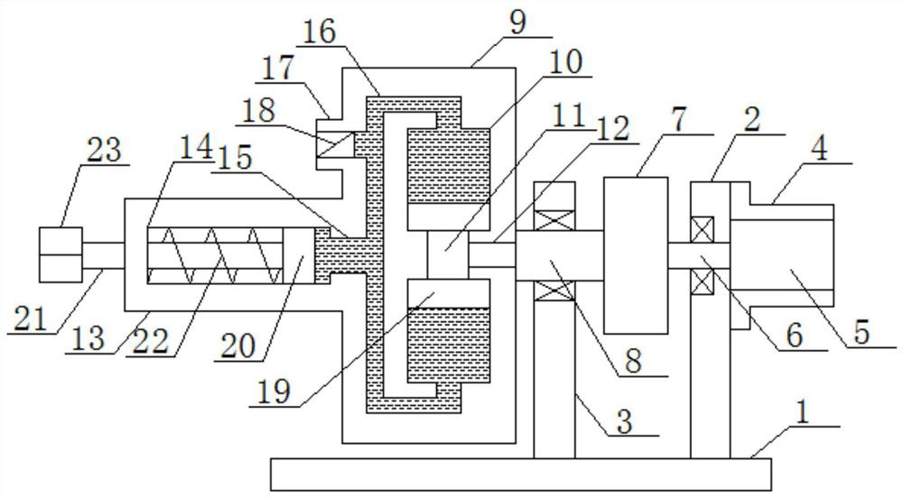
[0021] see figure 1 , an embodiment provided by the present invention: includes a bottom base plate 1, two parallel first vertical plates 2 and a second vertical plate 3 are installed on the upper surface of the bottom base plate 1, and the top of one side of the first vertical plate 2 Install a drive motor installation shell 4, a drive motor 5 is installed in the inside of the drive motor installation shell 4, the motor spindle 6 in the drive motor 5 runs through


PUM


Abstract

The invention discloses a tail driving device for centralized collection of particulate matter. The tail driving device comprises a bottom base plate. The device is used in cooperation with an adjustable front driving device for centralized collection of the particulate matter and can conduct angle control and driving collection work on particulate matter, so that the collection difficulty is reduced, and the collection efficiency is improved; meanwhile, the device is located at the tail to achieve a rotary propelling function, a front end mechanism can be telescopically propelled, and therefore collection of planar particulate matter is controlled; moreover, the device uses centrifugal force as pushing power, so that the speed can be controlled, then the propelling power is controlled, and the conversion rate is high; furthermore, the device is provided with a rotating strength effective control mechanism, so that the rotating strength can be effectively controlled, and excessive thrust caused by rotation is prevented; and in addition, the device is provided with an internal rolling type piston pushing mechanism, a centrifugal pushing effect at a correct angle can be achieved in the device, and therefore a more stable centrifugal pushing effect is achieved.

Description


Claims


Application Information

Patent Timeline
Owner 王佳平
Why Eureka
Try Eureka