Storage bin wall vibrating device
A vibrating device and silo wall technology, applied in the field of storage bins, can solve the problems of storage bins that are prone to accidents, sticky materials on the walls of the storage bins, and are difficult to clean, so as to reduce the time for cleaning the bins and solve the materials, and the effect of improving production efficiency
- Summary
- Abstract
- Description
- Claims
- Application Information
AI Technical Summary
Benefits of technology
Problems solved by technology
Method used
Image

Examples
Embodiment 1
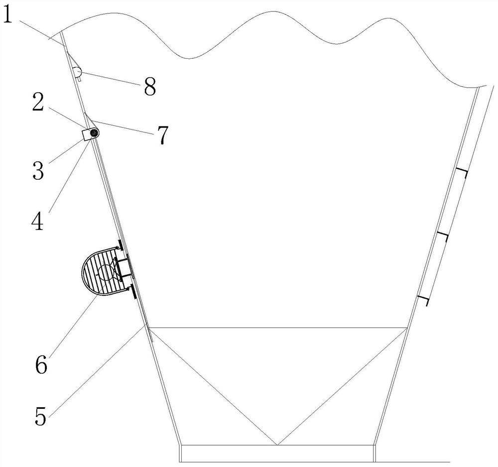
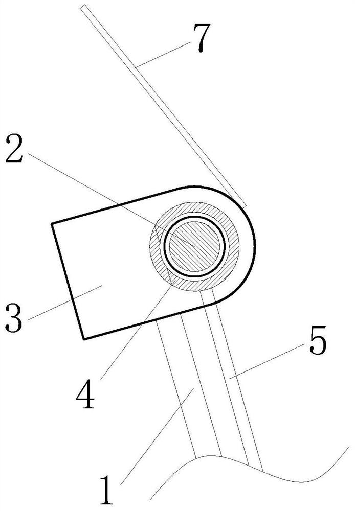
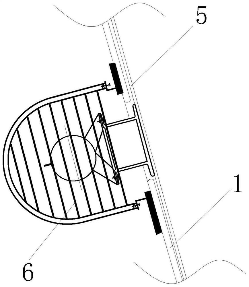
[0024] from Figure 1-3 It can be seen that the vibrating device for a silo wall in this embodiment includes a silo wall 1, the inner wall of the silo wall 1 is welded with a fixed rib plate 3, and the surface of the fixed rib plate 3 is fixedly provided with round steel 2 , The outer ring of the round steel 2 is fitted with a seamless steel pipe 4, the outer ring of the seamless steel pipe 4 is welded with a rapping steel plate 5, and the surface of the rapping steel plate 5 is equipped with a rapping motor 6.
[0025] The round steel 2 passes through the silo wall 1 through the fixed rib plate 3 and is double-sidedly welded on the silo wall.
[0026] The rapping motor 6 is installed on the rapping steel plate 5 inside the silo, and the base of the rapping motor 6 stretches out from the silo wall 1. When the rapping motor 6 works, it drives the rapping steel plate 5 to vibrate the silo wall 1, thereby The silo wall 1 vibrated vibrated material collapsed, in order to achieve the
Embodiment 2
[0031] from figure 1 It can be seen that the vibrating device for a silo wall in this embodiment includes a silo wall 1, the inner wall of the silo wall 1 is welded with a fixed rib plate 3, and the surface of the fixed rib plate 3 is fixedly provided with round steel 2 The outer ring of the round steel 2 is fitted with a seamless steel pipe 4, the outer ring of the seamless steel pipe 4 is welded with a rapping steel plate 5, the surface of the rapping steel plate 5 is equipped with a rapping motor 6, and the upper end of the fixed rib plate 3 is provided with a guide The flow plate 7, one end of the flow guide plate 7 is fixedly welded with the silo wall 1, and the flow guide plate 7 is obliquely arranged inside the silo wall 1. The deflector 7 can not only produce flow diversion, but also prevent the material from having a greater impact on the fixed rib plate 3. At the same time, a certain parabolic arc is generated during the blanking process, so that it can avoid sticking t
Embodiment 3
[0034] from Figure 4 It can be seen that the vibrating device for a silo wall in this embodiment includes a silo wall 1, the inner wall of the silo wall 1 is welded with a fixed rib 3, and the surface of the fixed rib 3 is fixedly provided with a round steel 2 , The outer ring of the round steel 2 is fitted with a seamless steel pipe 4, the outer ring of the seamless steel pipe 4 is welded with a rapping steel plate 5, and the surface of the rapping steel plate 5 is equipped with a rapping motor 6.
[0035] The side plate surface of the rapping steel plate 5 adjacent to the silo wall 1 is embedded with a U-shaped heating wire 51, and the U-shaped heating wire 51 is evenly distributed on the plate surface of the rapping steel plate 5, and the input end of the U-shaped heating wire 51 An electric heater 52 is connected. When the electric heater 52 does work, the U-shaped electric heating wire 51 generates heat. The rapping steel plate 5 has excellent thermal conductivity, thereby
PUM
 Abstract
Description
Claims
Application Information
 - R&D Engineer
- R&D Manager
- IP Professional
- Industry Leading Data Capabilities
- Powerful AI technology
- Patent DNA Extraction
Browse by: Latest US Patents, China's latest patents, Technical Efficacy Thesaurus, Application Domain, Technology Topic.
© 2024 PatSnap. All rights reserved.Legal|Privacy policy|Modern Slavery Act Transparency Statement|Sitemap