Heat exchange structure and semiconductor heat exchange device

A technology of heat exchange structure and heat exchange device, applied to indirect heat exchangers, heat exchanger shells, heat exchange equipment, etc., can solve problems such as difficult manufacturing and assembly, low heat exchange efficiency, complex structure, etc., and achieve convenient Manufacturing and assembly, improving heat exchange efficiency, and the effect of high heat exchange efficiency

Pending Publication Date: 2021-06-01
SHANGHAI MICRO ELECTRONICS EQUIP (GRP) CO LTD
View PDF7 Cites 0 Cited by
  • Summary
  • Abstract
  • Description
  • Claims
  • Application Information

AI Technical Summary

Benefits of technology

This patented technology allows for better control over fluids during their passage across different components without causing any issues or affects other parts' performance. It includes an openings at one end where there occurs thermal interference between neighbored streams of liquid, resulting in uneven movement caused by eddy currents within these flows. By creating this turbulance, it helps mix liquid with air more effectively than if they were only mixed together beforehand. Additionally, the design ensures efficient coolant circulations while maintaining good mixing characteristics. Overall, this innovative solution enhances the effectiveness of heat exchangers used in various industries such as chemical manufacturing processes.

Problems solved by technology

This patented technical problem addressed in this patents relates to improving the performance of semiconsoreceptors for use with electronic components during their cooling process due to its limited ability to absorb or release energy from either end without affecting other parts inside them.

Method used


Image

  • Heat exchange structure and semiconductor heat exchange device
  • Heat exchange structure and semiconductor heat exchange device
  • Heat exchange structure and semiconductor heat exchange device

Examples


Embodiment Construction

[0033] In order to make the purpose, technical solutions and advantages of the embodiments of the present invention clearer, the technical solutions in the embodiments of the present invention will be clearly and completely described below in conjunction with the drawings in the embodiments of the present invention. Obviously, the described embodiments It is a part of embodiments of the present invention, but not all embodiments. The components of the embodiments of the invention generally described and illustrated in the figures herein may be arranged and designed in a variety of different configurations.

[0034] Accordingly, the following detailed description of the embodiments of the invention provided in the accompanying drawings is not intended to limit the scope of the claimed invention, but merely represents selected embodiments of the invention. Based on the embodiments of the present invention, all other embodiments obtained by persons of ordinary skill in the art witho


PUM


Abstract

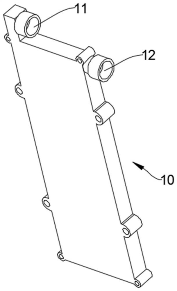
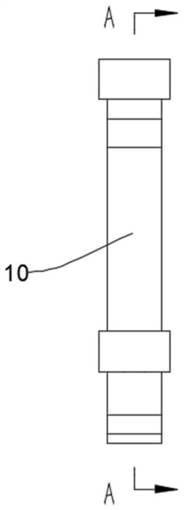
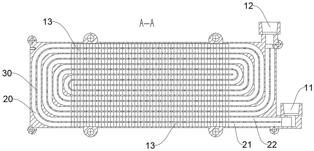
The invention discloses a heat exchange structure and a semiconductor heat exchange device, and belongs to the technical field of semiconductor refrigeration. The heat exchange structure comprises a heat exchange body and a heat exchange flow channel arranged in the heat exchange body. Fins are arranged in the heat exchange flow channel, and the fins are arranged in the heat exchange flow channel to divide the heat exchange flow channel into at least two sub-flow channels in the flowing direction. Heat exchange through holes are formed in the side walls of the fins so that every two adjacent sub-flow channels can communicate with each other. According to the heat exchange structure, through the arrangement of the perforated fins, fluid in every two adjacent sub-flow channels can generate disturbance, laminar heat transfer of original fluid is destroyed, the fluid does irregular motion to form turbulent flow, the fluid is transited from a laminar flow area to a turbulent flow area in advance, heat transfer of the fluid in a transition area and a turbulent flow area is enhanced, and the heat exchange efficiency is improved.

Description


Claims


Application Information

Patent Timeline
Owner SHANGHAI MICRO ELECTRONICS EQUIP (GRP) CO LTD
Why Eureka
Try Eureka