Method for supporting ultra-thin roof roadway under goaf

A technology for roadway support and goaf, which is applied in the field of extremely thin roof roadway support under the goaf, which can solve the problems of easy falling off of roof anchor components, easy damage of supporting structure, and low supporting efficiency, so as to reduce falling off Probability of failure, enhanced strength, and the effect of saving support costs

Inactive Publication Date: 2021-06-04
新疆维吾尔自治区煤炭科学研究所
View PDF0 Cites 1 Cited by
  • Summary
  • Abstract
  • Description
  • Claims
  • Application Information

AI Technical Summary

Benefits of technology

This patented device solves problems such as over-pressured roads caused by heavy traffic or poorly formed lanes due to rocks falling into them during construction work. It uses an expandible tube made up of two parts - one part contains a spring mechanism for adjustability and another part holds a rubber material called a cushing block. When there're no weight on it, they stay at their original position because they don’t compress too much like regular pneumatic tubings used today. However if someday some heavier objects fall onto this new design, the force from gravity causes the bottom section to break down create cracks within the structure without being able to absorb any more energy than usual. By adding a special type of anchoring system, which helps stabilizing these areas around the crack opening, the supporting effect becomes even stronger against impact loads. Additionally, the patents propose various methods for filling the space between the tire ring and the ground surface before casting concrete, resulting in improved load distribution and increased bearing capacities. Overall, the technical effects include efficient and reliable support systems for vehicles equipped with wheels, enhancing safety standards, preventive maintenance costs reduction, better vehicle performance, lessened damage to nearby structures, and lower risk of accidents associated with unsteady pavement conditions.

Problems solved by technology

This patented technology describes how to safely support tunneling cars during excavation operations on highly-thin or thick walls that may develop cracks over time caused by repeated stress cycles like drilling holes through soil layers. Current methods involve use channels made up mostly of iron wires embedded into concrete slabs, but this method has limitations such as being too rigid at times causing damage to other structures near them while also requiring extra work effort compared to more flexible alternatives like metal pipes.

Method used


Image

  • Method for supporting ultra-thin roof roadway under goaf
  • Method for supporting ultra-thin roof roadway under goaf
  • Method for supporting ultra-thin roof roadway under goaf

Examples


Embodiment

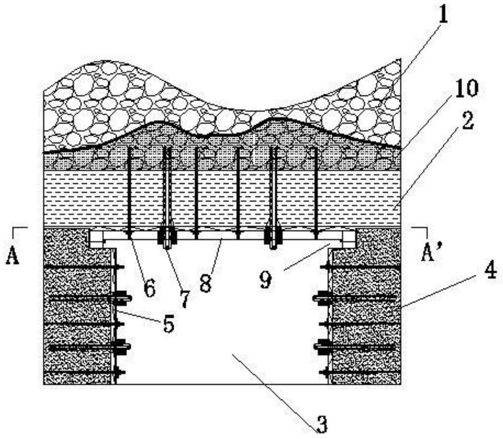
[0033] A method for supporting roadways with extremely thin roofs in goafs, comprising the following steps.

[0034] Step 1. Through theoretical calculation, the periodical compressive load q on the roof of roadway 3 is obtained, and the calculation formula of q is: q=kMγ / (k p -1) , where: k is the dynamic load coefficient of the roof period, generally 1.2~2.0 (can be determined according to the monitoring data of the adjacent working face mine pressure); M is the thickness of the coal seam; k p Roof rock breaking expansion coefficient; γ average bulk density of roof rock layer.

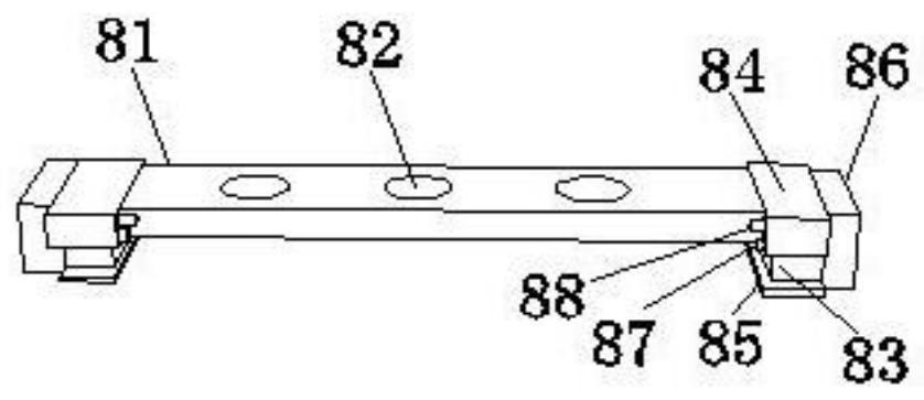
[0035] Step 2, according to the cross-sectional size of the roadway 3 and the roof period calculated in the step 1, the compression load q is used to make the pressure beam 8, specifically: see image 3 , let pressure beam 8 be made up of channel steel 81, piston 83, telescopic cylinder 84, support plate 85, buffer pad 86; Channel steel 81 is provided with round hole 82; Connect the piston 83, the p


PUM

PropertyMeasurementUnit
Hole diameteraaaaaaaaaa
Thicknessaaaaaaaaaa
Diameteraaaaaaaaaa

Abstract

The invention relates to the field of coal mining roadway support, and provides a method for supporting an ultra-thin roof roadway under a goaf. The method comprises the following steps of: step 1, obtaining a periodic weighting load of a roadway roof through a theoretical calculation formula; step 2, manufacturing a yielding beam according to the section size of the roadway and the periodic weighting load of the roof obtained in step 1; step 3, conducting a grouting anchor cable pre-grouting test on a roof of an excavated roadway, and obtaining the optimal grouting pressure and the optimal slurry diffusion radius; step 4, installing a grouting anchor cable and a threaded steel anchor rod on roadway sides for reinforcement, and digging beam nests in the tops of the roadway sides; and step 5, installing the yielding beam in the beam nests fixing the yielding beam to the roadway roof through the grouting anchor cable, and then installing the threaded steel anchor rod on the edge of one side of the yielding beam, so as to complete roadway roof supporting. The technical problems that in an existing supporting technology, a supporting structure is prone to damage, a roof anchoring component is prone to falling off, the labor intensity is large, and the supporting efficiency is low can be effectively solved.

Description


Claims


Application Information

Patent Timeline
Owner 新疆维吾尔自治区煤炭科学研究所
Why Eureka
Try Eureka