Clamping device for fusion welding of automobile part

An auto parts, fusion welding technology, applied in auxiliary devices, welding equipment, auxiliary welding equipment and other directions, can solve the problems of unsatisfactory fixing effect, low work efficiency, and inability to adjust the fixed angle of welding parts, so as to improve work efficiency and improve work efficiency. Welding accuracy, the effect of wide applicability

Pending Publication Date: 2021-06-18
上海贸迎新能源科技有限公司
View PDF0 Cites 0 Cited by
  • Summary
  • Abstract
  • Description
  • Claims
  • Application Information

AI Technical Summary

Benefits of technology

The technical effect described by this patented technology allows multiple sets of wires or rods are loaded onto certain components while they stay fixed together accurately without requiring manual labor. This helps improve overall performance and reduces downtime caused due to maintenance issues. Additionally, it enables remote control over movement based upon needs such as centering between specific points within the component being joined (the cone) and adjustable angles at various locations around them.

Problems solved by technology

In current methods used for fused weldings between sheets of material like steel plate, there can be issues where certain angles cannot match properly during assembly because they require specific tools that may have difficulty fitting them correctly. Additionally, these processes often involve manual labor and slow down production times. Therefore an improved solution needs to be developed without requiring expensive equipment.

Method used


Image

  • Clamping device for fusion welding of automobile part
  • Clamping device for fusion welding of automobile part
  • Clamping device for fusion welding of automobile part

Examples


Embodiment

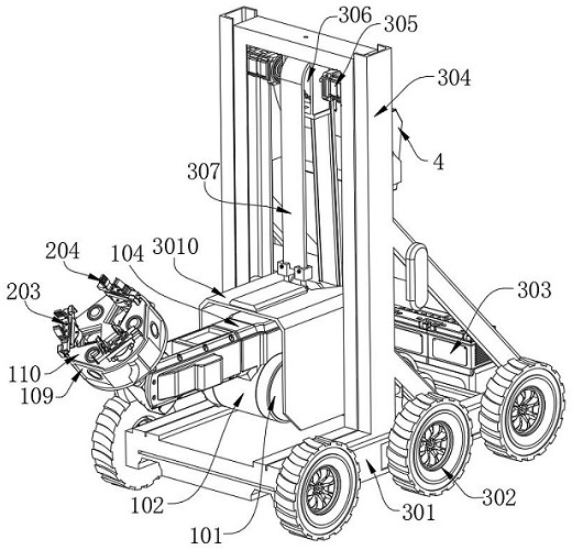
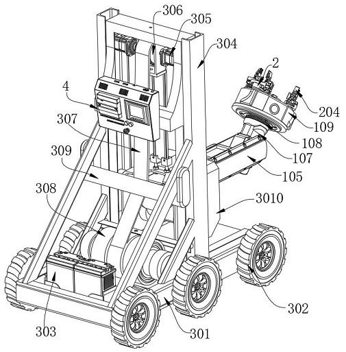
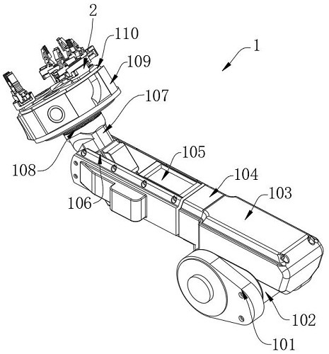
[0032] see Figure 1-9 , the present invention provides a technical solution: a clamping device for fusion welding of auto parts, including a clamping mechanism 1, a carrying mechanism 3 and a controller 4, and the clamping mechanism 1 includes a first support plate 101, a first motor 102 , first hinge arm 103, second motor 104, second hinge arm 105, third motor 106, third hinge arm 107, fourth motor 108, storage table 109, servo motor 1103, bevel worm gear 1104, three bevel worms 1105, three lead screws 1106, three sliders 1107 and three asynchronous motors 2, the inside of the first brace 101 is connected with the first motor 102 by screws, the upper surface of the first brace 101 is connected with the first hinge arm The lower surface of 103 is welded, the front surface of the first hinge arm 103 is connected with the second motor 104 by screws, the output shaft of the second motor 104 is welded with the inner side wall of the second hinge arm 105, and the inner side wall of t


PUM


Abstract

The invention discloses a clamping device for fusion welding of an automobile part. The clamping device comprises a clamping mechanism, a carrying mechanism and a controller, wherein the clamping and fixing mechanism comprises a first supporting plate, a first motor, a first hinge arm, a second motor, a second hinge arm, a third motor, a third hinge arm, a fourth motor, a storage table, a servo motor, a bevel worm gear, three bevel worms, three lead screws, three sliding blocks and three asynchronous motors, and the interior of the first supporting plate is in threaded connection with the first motor through a screw. The servo motor, the bevel worm gear, the bevel worms, the lead screws, the sliding blocks and calipers in the clamping mechanism are matched, so that the requirement for clamping and displacement splicing of multiple sets of welding parts loaded at the same time is met, the requirement for precise centering of the distance between the parts can be met through the bevel worm gear in the displacement period, and the relative angle between the parts can be adjusted freely through the asynchronous motors, so that workers are assisted in completing the welding task.

Description


Claims


Application Information

Patent Timeline
Owner 上海贸迎新能源科技有限公司
Why Eureka
Try Eureka