Current feedback control method and system of load-end constant-voltage rectification power supply
A technology of rectifying power supply and current feedback, applied in the field of power supply, to achieve the effect of simplifying power supply equipment, controlling cost increase and improving reliability
- Summary
- Abstract
- Description
- Claims
- Application Information
AI Technical Summary
Problems solved by technology
Method used
Image

Examples
Example Embodiment
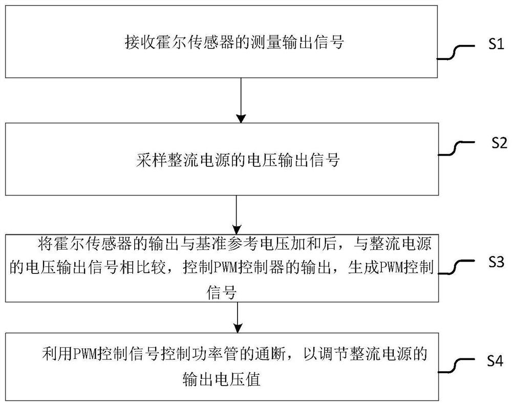
[0052] Example 1:
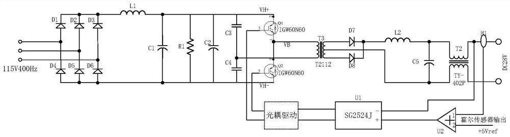
[0053] First, convert the external three-phase intermediate frequency power supply into a DC power supply through a power conversion circuit;
[0054] The input coil end of the Hall sensor is coupled with the output end of the power conversion circuit, the Hall sensor is used to measure the magnitude of the load current, and a measurement signal proportional to the load current is output.
[0055] like figure 2As shown, after receiving the load current measurement signal of the Hall sensor, the load current sampling voltage is added to the pre-defined +5Vref reference voltage, and the signal generated by the adder is sent to the U1 chip SG2524J, which is the same phase of the PWM controller. In addition, the output voltage of the regulated power supply is sampled to the inverting input terminal of the U1 chip, and the PWM control signal is generated by the U1 chip according to the amplitude of the in-phase and inverting input; the specific steps of generatin
Example Embodiment
[0058] Example 2:
[0059] Based on the inventive concept of the specific embodiment, this embodiment 2 provides a current feedback control system for a constant-voltage rectifier power supply at a load end, and the system includes:
[0060] The acquisition module is used to receive the measurement output signal of the Hall sensor;
[0061] The sampling module is used to sample the voltage output signal of the rectified power supply;
[0062] The control module is used for adding the output of the Hall sensor and the reference voltage, and comparing it with the voltage output signal of the rectifier power supply to control the output of the PWM controller to generate a PWM control signal;
[0063] The regulating module is used to control the on-off of the power tube by using the PWM control signal to regulate the output voltage value of the rectified power supply.
[0064] Among them, the acquisition module includes:
[0065] The conversion module is used to convert the extern
PUM
 Abstract
Description
Claims
Application Information
 - R&D Engineer
- R&D Manager
- IP Professional
- Industry Leading Data Capabilities
- Powerful AI technology
- Patent DNA Extraction
Browse by: Latest US Patents, China's latest patents, Technical Efficacy Thesaurus, Application Domain, Technology Topic.
© 2024 PatSnap. All rights reserved.Legal|Privacy policy|Modern Slavery Act Transparency Statement|Sitemap