Optical film and camera module

An optical film and filter film technology, applied in the field of optical imaging, can solve the problems of the warped reflectivity of the optical film film, affecting the imaging effect of the camera module, etc., to achieve a good imaging effect, reduce the flash phenomenon, and improve the reflection. higher rate effect

Inactive Publication Date: 2021-07-09
NANCHANG O FILM OPTICAL ELECTRONICS TECH CO LTD
View PDF14 Cites 0 Cited by
  • Summary
  • Abstract
  • Description
  • Claims
  • Application Information

AI Technical Summary

Benefits of technology

This patented technology describes an improved camera system that uses multiple layers for improving its performance. One layer consists mainly of enhanced films made from materials like silicon nitride or fluorine-containing polymers on top of another material called glass. Another layer includes filters with different types of coatings such as aluminum oxide (Al2O3) or titanium dioxide (Ti02). These improvements help prevent distortion caused during exposure while still allowing good quality images captured through the cameras' sensors. Additionally, this design helps reduce reflection at certain angles causing issues when capturing clear pictures due to poor focus conditions. Overall these technical features contribute towards better overall functionality and reliability of the camera systems used today.

Problems solved by technology

This patented describes how cameras use filters in their components for capturing better quality pictures by filtering off certain parts of the sunlight or reflected glare caused by nearby objects during photography. These issues lead to poorer performance when taking photos due to distortion of the captured picture being displayed at another location near it.

Method used


Image

  • Optical film and camera module
  • Optical film and camera module
  • Optical film and camera module

Examples


Embodiment Construction

[0036] In order to facilitate the understanding of the present application, the present application will be described more fully below with reference to the relevant drawings. Preferred embodiments of the application are shown in the accompanying drawings. However, the present application can be embodied in many different forms and is not limited to the embodiments described herein. On the contrary, the purpose of providing these embodiments is to make the disclosure of the application more thorough and comprehensive.

[0037] It should be noted that when an element is referred to as being “fixed” to another element, it can be directly on the other element or there can also be an intervening element. When an element is referred to as being "connected to" another element, it can be directly connected to the other element or intervening elements may also be present. The terms "inner", "outer", "left", "right" and similar expressions are used herein for the purpose of description


PUM

PropertyMeasurementUnit
Thicknessaaaaaaaaaa
Thicknessaaaaaaaaaa
Thicknessaaaaaaaaaa

Abstract

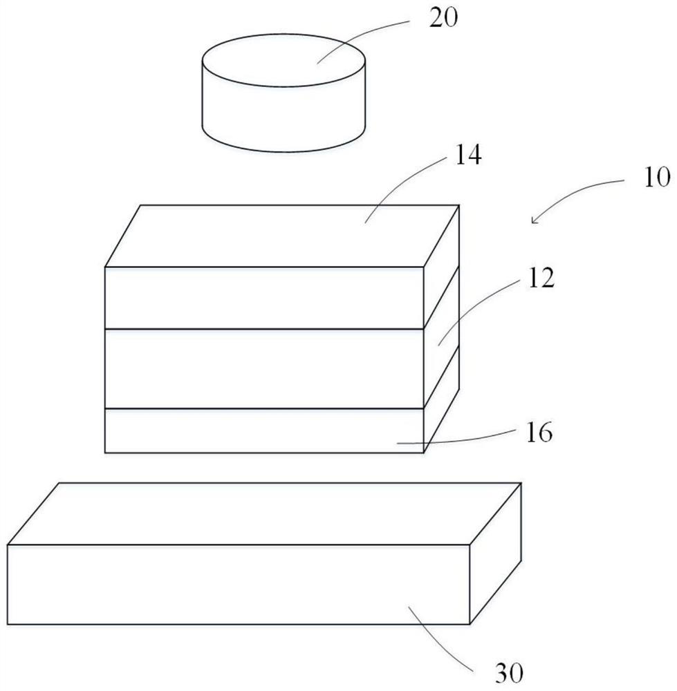
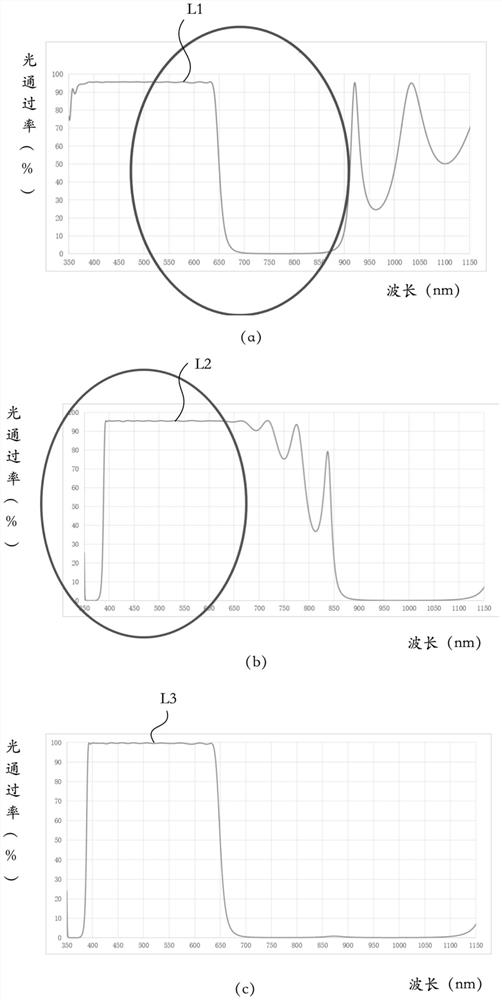
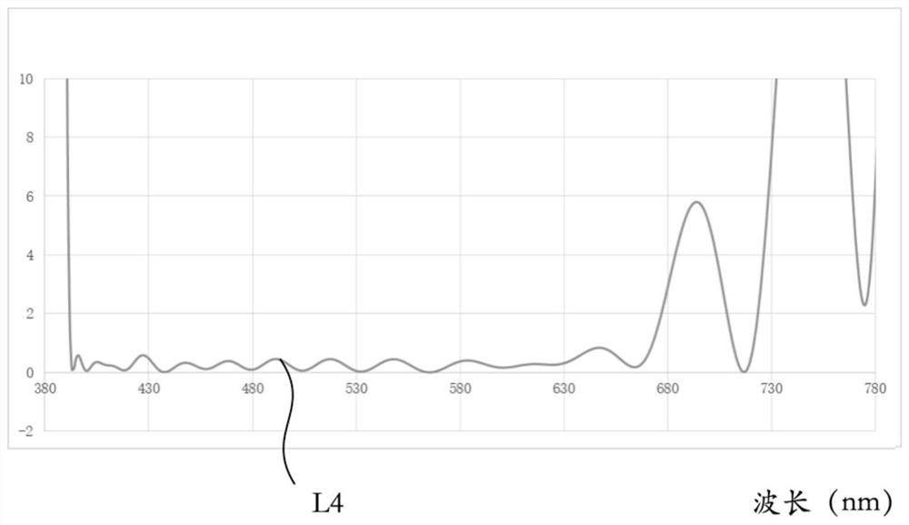
The invention relates to an optical film and a camera module. The optical film comprises a base material, a filter film and an anti-reflection film. The base material comprises a first surface and a second surface located on the opposite side of the first surface. The filter film is arranged on the first surface. The anti-reflection film is arranged on the second surface and comprises an anti-reflection film body and a thickening film layer stacked on the anti-reflection film body, the anti-reflection film body is used for improving the passing rate of preset light, and the thickening film layer is used for improving the thickness of the anti-reflection film so as to reduce warping of the optical film. The thickness of the anti-reflection film is increased by arranging the thickening film layer, so that the warping phenomenon of the optical film caused by the large thickness difference between the anti-reflection film and the filter film can be avoided. Meanwhile, the anti-reflection film can also improve the problem that the reflectivity of the side, provided with an image sensor, of the optical film is high and relieve the flash phenomenon, so that the camera module using the optical film can obtain a better imaging effect.

Description


Claims


Application Information

Patent Timeline
Owner NANCHANG O FILM OPTICAL ELECTRONICS TECH CO LTD
Why Eureka
Try Eureka