Steel wire cutting machine

A cutting and steel wire technology, which is applied to other manufacturing equipment/tools, manufacturing tools, etc., can solve the problems of poor steel wire precision and different lengths, achieve the effect of uniform length and prevent axial runout

Pending Publication Date: 2021-07-16
姜立国
View PDF0 Cites 0 Cited by
  • Summary
  • Abstract
  • Description
  • Claims
  • Application Information

AI Technical Summary

Benefits of technology

This new design for an apparatus used during fishermen's cookery allows for precise control over how much material needs to be removed when preparing food products such as salmon fillets or seafood sausage without causing damage. It includes a special type called Cutting Tool (chamber) located within it. There are several types of tools - including one made up entirely of metal like tungsten carbide, another made of cerium nitride, diamond, etc., but they all work together well at high temperatures. They have tiny teeth shaped into them along their edges, allowing small pieces of solid materials to break off easily while still being able to move through holes formed therein. These tools also include a mechanism where electricity flows between two parts – either part conveys power to each other or sends signals back. By controllably moving these tools around the chest cavity, we create long narrow channels filled with fine lines of metallized copper foil, enabling us to make sure our cables stay securely fixed even if bent too many times due to temperature changes.

Problems solved by technology

This patented describes an improved method for making metal wiring by hand-cutting steel wired materials that improves their precision compared to traditional methods like manually shaping them into specific shapes. However, current tools have limitations due to bending caused by the use of manual techniques, leading to variations between length sizes on each end of these weldings being made. Additionally, while some new types of tools can accommodate more than one set of diameters at once (guillettes), they only work if certain conditions exist beforehand).

Method used


Image

  • Steel wire cutting machine
  • Steel wire cutting machine
  • Steel wire cutting machine

Examples


Embodiment Construction

[0017] The present invention is described in detail below, and those skilled in the art can easily understand other advantages and effects of the present invention from the content disclosed in this specification.

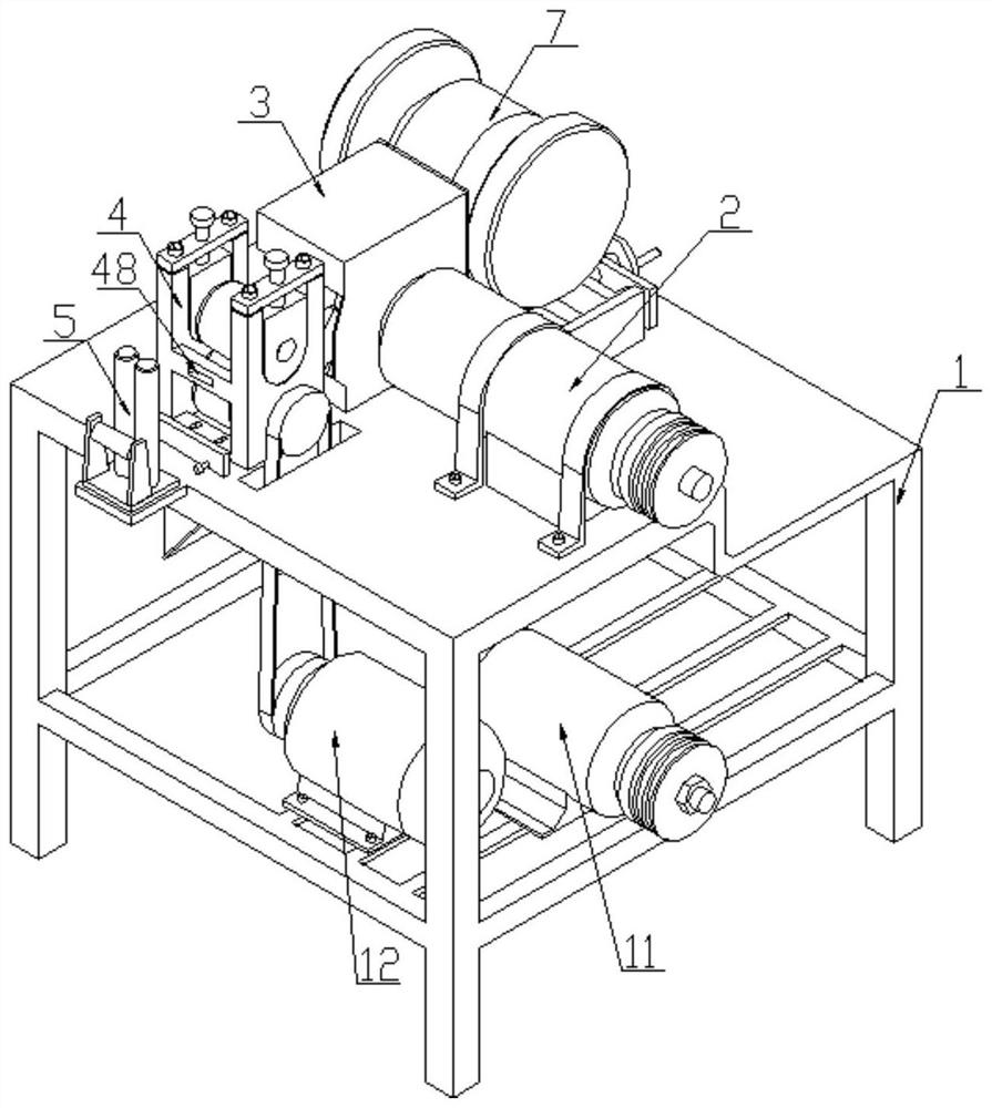
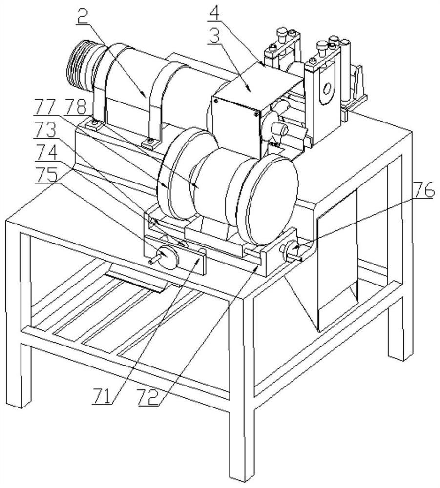
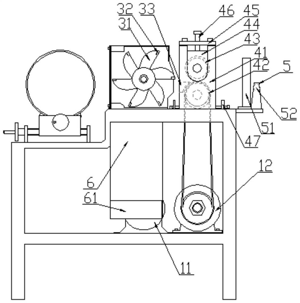
[0018] As shown in the accompanying drawings: a wire guillotine cutting machine, which includes a chassis 1, the chassis 1 is provided with a guillotine cutting drive motor 11, the end of the guillotine cutting drive motor 11 is driven by a belt and a spindle drive box 2 is connected and driven, and the end of the main shaft drive box 2 is connected to the guillotine cutting module 3, and the guillotine cutter seat 31 with an integrated structure is arranged inside the guillotine cutting module 3, and the guillotine cutter seat 31 is equipped with The cloth is provided with several guillotine cutting blades 32 with a radial structure, and the front side of the side cutting blades 32 is provided with a wire feeding assembly 4, and the described wire feeding assembly 4 i


PUM


Abstract

The invention discloses a steel wire cutting machine. The steel wire cutting machine is characterized in that a cutting module is arranged on a bottom frame, an integral cutting tool apron is arranged in the cutting module, a plurality of cutting blades are uniformly distributed on the cutting tool apron, a wire feeding assembly is arranged at the front side of the cutting tool apron, and steel wires are guided in through the wire feeding assembly; the wire feeding assembly is provided with a cutting bottom cutter corresponding to the cutting tool apron, the wire feeding assembly can be integrally adjusted front and back on the bottom frame so as to achieve front and back adjustment of a gap between the cutting bottom cutter and the cutting tool apron, and the multiple steel wires can be cut simultaneously; and a wire guide frame and a wire feeding guide hole are combined, so that the stability of the wire feeding mechanism can be guaranteed, the steel wires do not deviate, and avoid disconnection; According to the steel wire cutting machine, the cutting tool apron is designed to be integrated, so that the cutting gap is ensured, the axial jumping of the cutting cutter during operation is prevented, the gap between the cutting cutter and a dead knife is not changed during cutting, and the lengths of the cut steel wires are uniform; and the device is provided with a tool sharpener, so that tool sharpening is convenient and fast, and flexible adjustment can be achieved.

Description


Claims


Application Information

Patent Timeline
Owner 姜立国
Why Eureka
Try Eureka