Municipal rainwater drainage device capable of avoiding blockage and rainwater drainage method

A technology for avoiding clogging and draining devices, applied in water supply devices, water/sewage treatment, chemical instruments and methods, etc., can solve problems such as rainwater cannot be discharged in time, drainage wells are blocked, and vehicle traffic is affected

Active Publication Date: 2021-07-23
广东乐华建设工程有限公司
View PDF12 Cites 3 Cited by
  • Summary
  • Abstract
  • Description
  • Claims
  • Application Information

AI Technical Summary

Benefits of technology

This patented technology allows multiple water tanks are combined with an angled shelf placed at one end near each other along its length. These tunnels help direct rainwater towards specific areas where there may be heavy traffic or snowfall during winter months. They also have holes made up by different materials like metal pipes or plastic tubings filled with sand filler. By placing these structures alongside roadside sides they ensure proper placement without blocking any open spaces around them while still allowing some amount of rainflow through.

Problems solved by technology

This patented technical problem addressed by this patents relates to preventing damage caused from heavy precipitation or debris entering storm draining systems due to blocked pipes overlooking areas where they may collect excessive amounts of liquid waste such as sewages overflowing through them.

Method used


Image

  • Municipal rainwater drainage device capable of avoiding blockage and rainwater drainage method
  • Municipal rainwater drainage device capable of avoiding blockage and rainwater drainage method
  • Municipal rainwater drainage device capable of avoiding blockage and rainwater drainage method

Examples


Embodiment 1

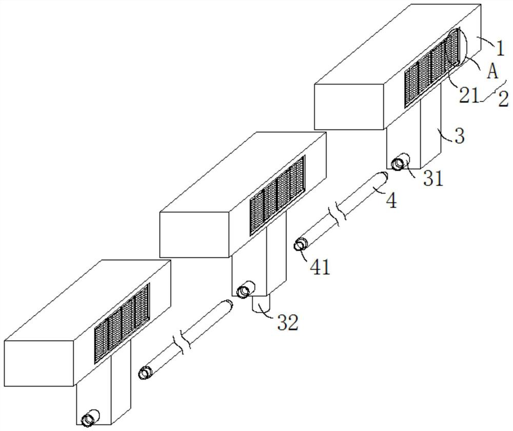
[0029] see Figure 1-4 , this embodiment provides a municipal rainwater drainage device and rainwater drainage method that can avoid clogging, including several drainage seats 1 and anti-clogging mechanisms 2, several drainage seats 1 are bonded together, and the drainage seats 1 are located on the road subgrade The edge is used as a protective seat, and the right end face of the drain seat 1 is provided with an L-shaped drain hole 11, and the L-shaped drain hole 11 communicates with the right end face and the bottom end face of the drain seat 1, and several drain seats 1 are bonded together, and The drainage seat 1 is installed on the side of the roadside subgrade to ensure that the lowest point of the opening on the right side of the L-shaped weep hole 11 is lower than the height of the road surface, so that rainwater can flow into the L-shaped weep hole 11 so as to realize quick alignment. Rainwater for drainage purposes.

[0030] Compared with the traditional way of using ma

Embodiment 2

[0039] see Figure 1-4 , further improvements have been made on the basis of Example 1:

[0040] In order to solve the problem of how to avoid rainwater leakage, the tip of the water guide pipe 31 is provided with a subsidence type docking groove, and the connecting pipe 4 is extended at both ends in the axial direction with a butt joint pipe 41 seamlessly inserted into the inside of the subsidence type docking groove, and the connection is provided with The gasket is seamlessly inserted into the submerged docking groove of the butt joint pipe 41 and the water guide pipe 31, and a gasket is provided at the joint, which can enhance the connection tightness between the water guide pipe 31 and the connecting pipe 4.

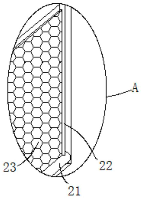
[0041] In order to solve the problem of how to prevent impurities from crossing the first filter screen 23 and entering the L-shaped drain hole 11, the heights of the first filter screen 23 and the second filter screen are equal, and both are at the right opening heigh


PUM


Abstract

The invention discloses a municipal rainwater drainage device capable of avoiding blockage and a rainwater drainage method, and relates to the technical field of municipal rainwater drainage. The municipal rainwater drainage device comprises a plurality of drainage bases and an anti-blockage mechanism, the drainage bases are attached together, L-shaped drainage holes are formed in the right end faces of the drainage bases, connecting bases are perpendicularly arranged on the drainage bases, the anti-blockage mechanism comprises a rotating roller, a plurality of evenly-distributed first supporting rods are arranged at the highest point of the radial side wall of the rotating roller, and a first filter screen capable of filtering rainwater impurities at the right side openings of the L-shaped drainage holes is arranged between every two adjacent first supporting rods. According to the municipal rainwater drainage device capable of avoiding blockage and the rainwater drainage method, the plurality of drainage bases are attached together and installed at the side position of a roadside roadbed, it is ensured that the lowest point of a right opening of each L-shaped drainage hole is lower than the height of the road surface, rainwater conveniently flows into the L-shaped drainage holes, meanwhile, impurity particles in the rainwater are prevented from entering the L-shaped drainage holes through the anti-blockage mechanism, the L-shaped drainage holes are prevented from being blocked, and therefore, the purpose of rainwater drainage is achieved.

Description


Claims


Application Information

Patent Timeline
Owner 广东乐华建设工程有限公司
Why Eureka
Try Eureka