Printer screw tightening equipment

A printer and screw technology, which is applied in the field of printer screw tightening equipment, can solve problems such as high labor intensity, wrong screw tightening, and defects, and achieve the effect of improving efficiency, quality, and efficiency

Pending Publication Date: 2021-07-27
苏州华维乐自动化科技有限公司
View PDF15 Cites 0 Cited by
  • Summary
  • Abstract
  • Description
  • Claims
  • Application Information

AI Technical Summary

Problems solved by technology

[0003] At present, for the screwing process of the printer, the screws are all manually screwed, and the screw is often screwed wrong, resulting in d

Method used


Image

  • Printer screw tightening equipment
  • Printer screw tightening equipment
  • Printer screw tightening equipment

Examples


Embodiment Construction

[0040] In order to make the purpose, technical solution and advantages of the present invention more clear, the present invention will be further described in detail below in conjunction with the accompanying drawings and embodiments. It should be understood that the specific embodiments described here are only used to explain the present invention, not to limit the present invention.

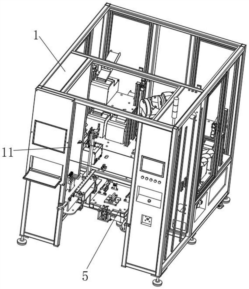
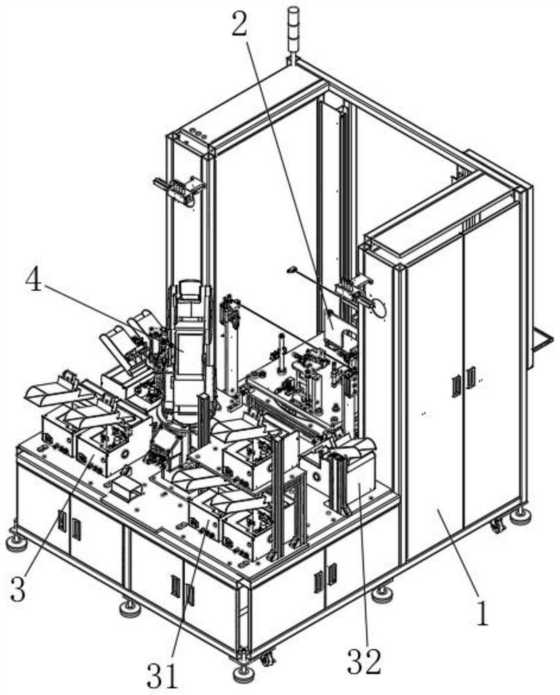
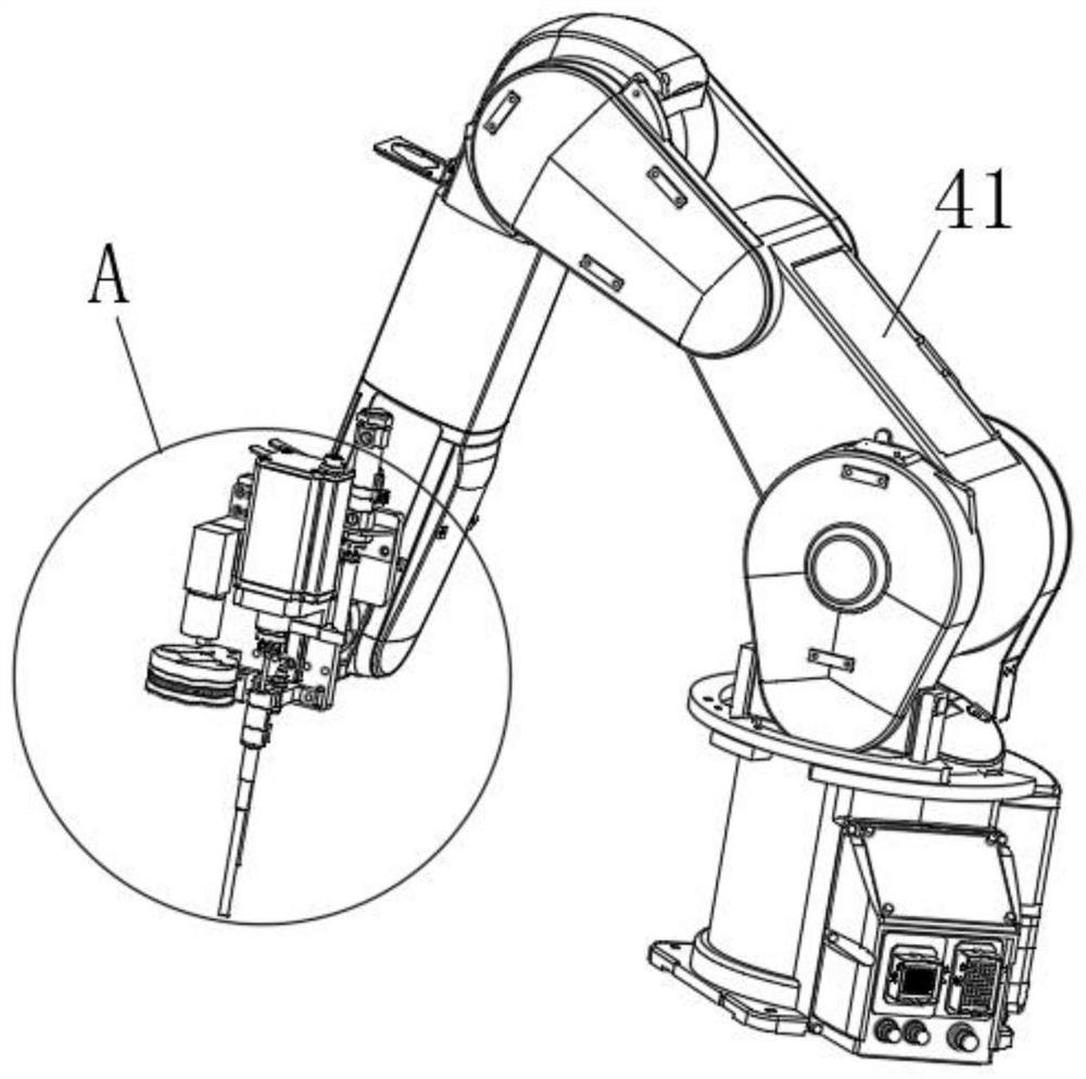
[0041] This example refers to Figure 1 to Figure 14 As shown, it includes a frame 1 and a positioning trolley module 2; the frame 1 is connected with a screw feeding module 3, an automatic adsorption screwing module 4, and a positioning and rotating material receiving module 5; the positioning trolley module 2 is used for positioning the printer Clamping; the positioning rotary material receiving module 5 is used to position and fix the positioning trolley module 2, and drive the rotating end of the positioning trolley module 2 to rotate; the automatic adsorption screwing module 4 is used to load


PUM


Abstract

The invention relates to printer screw tightening equipment which comprises a rack and a positioning trolley module. The rack is connected with a screw feeding module, an automatic adsorption screw tightening module and a positioning rotary material receiving module. The positioning trolley module is used for positioning and clamping a printer. The positioning rotary material receiving module is used for positioning and fixing the positioning trolley module and driving the rotary end of the positioning trolley module to rotate. The automatic adsorption screw tightening module is used for adsorbing screws fed by the screw feeding module and tightening the screws on the printer. According to the printer screw tightening equipment, the screw feeding module is adopted for feeding, then automatic screw tightening is conducted on products on the positioning trolley module through the automatic adsorption screw tightening module, and the products are driven to rotate in cooperation with the positioning rotary material receiving module, so that screw tightening is conducted on the four faces of the printer at a time, and the efficiency and the quality are improved.

Description


Claims


Application Information

Patent Timeline
Owner 苏州华维乐自动化科技有限公司
Why Eureka
Try Eureka