Water-cooling laser integrated welding cabinet

A laser, all-in-one technology, used in laser welding equipment, welding equipment, metal processing equipment, etc., can solve the problem of inconvenient movement and fixation of the all-in-one machine

Inactive Publication Date: 2021-08-20
武汉蓝晶优创激光科技有限公司
View PDF6 Cites 0 Cited by
  • Summary
  • Abstract
  • Description
  • Claims
  • Application Information

AI Technical Summary

Benefits of technology

The invention provides an improved way for devices that are flexible enough but still easy to use without being limited by their placement on surfaces or other objects they're attached to. This makes it easier than ever before to create more versatile solutions with different types of tools like screws or bolts.

Problems solved by technology

This patented describes two technical problem addressed by this patents: current single piece liquid crystal display (LCD) cabinets are difficult or expensive to carry around due to their weight and lack of stability when they hit hard surfaces on uneven ground. Additionally, these LCDs may get damaged if dropped from heights while being carried over long distances without proper care.

Method used


Image

  • Water-cooling laser integrated welding cabinet
  • Water-cooling laser integrated welding cabinet
  • Water-cooling laser integrated welding cabinet

Examples


Embodiment Construction

[0019] In order to enable those skilled in the art to better understand the solution of the present application, the technical solution in the embodiment of the application will be clearly and completely described below in conjunction with the accompanying drawings in the embodiment of the application. Obviously, the described embodiment is only It is an embodiment of a part of the application, but not all of the embodiments. Based on the embodiments in this application, all other embodiments obtained by persons of ordinary skill in the art without creative efforts shall fall within the scope of protection of this application.

[0020] It should be noted that the terms "first" and "second" in the description and claims of the present application and the above drawings are used to distinguish similar objects, but not necessarily used to describe a specific sequence or sequence. It should be understood that the data so used may be interchanged under appropriate circumstances for th


PUM


Abstract

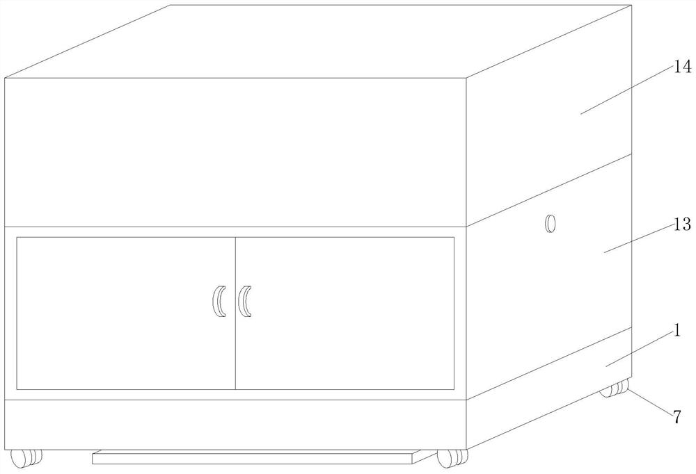
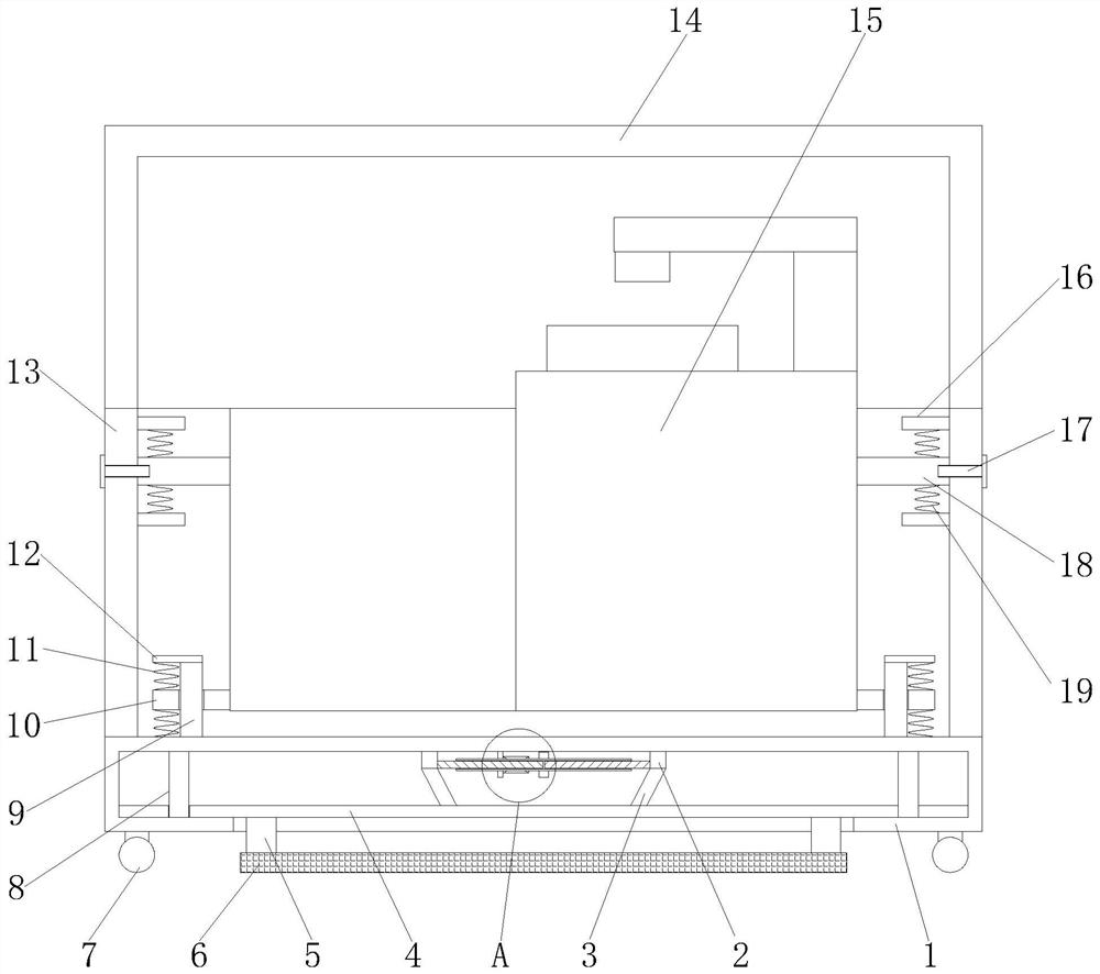
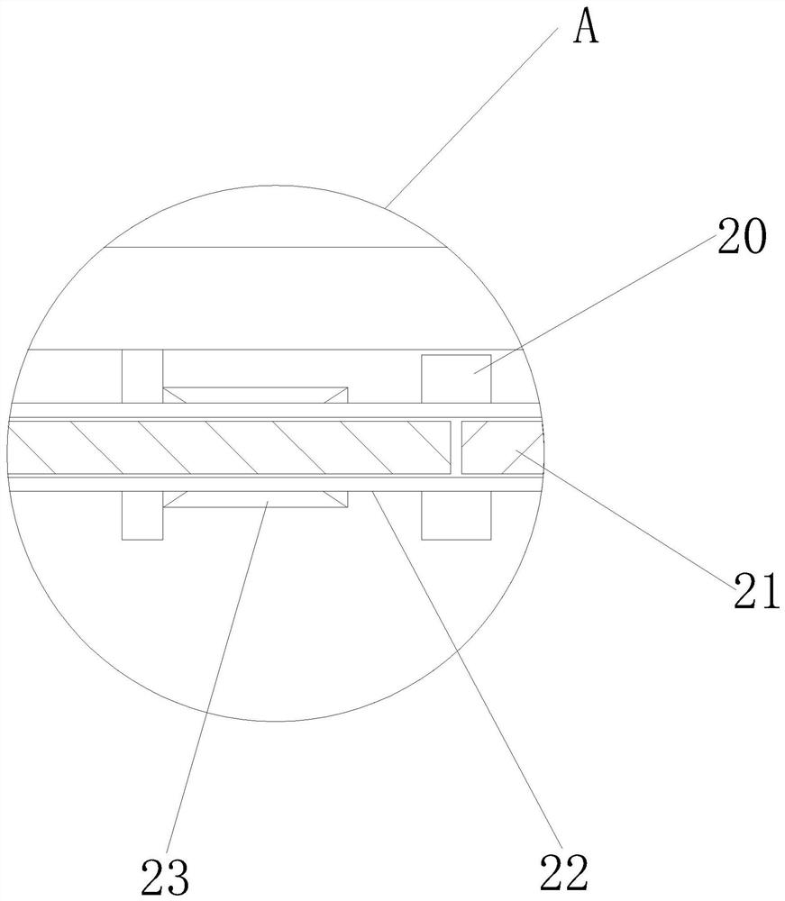
The invention discloses a water-cooling laser integrated welding cabinet which comprises a supporting table. Pulleys are fixedly connected to the four corners of the bottom end of the outer wall of the supporting table correspondingly, the top end of the supporting table is fixedly connected to the bottom end of the outer wall of a box body, the top end of the box body is clamped to the bottom end of a box cover, the left side and the right side of the top end of the supporting table are fixedly connected to the bottom ends of fixing rods correspondingly, and the outer walls of the two fixing rods are slidably connected to the centers of sleeve plates in a sleeved mode. The water-cooling laser integrated welding cabinet is reasonable in structure, a rotating motor is started, the rotating motor drives gears to rotate, the two gears are matched in a meshing mode to rotate together, the gears drive a cavity shaft to rotate, and two threaded rods in threaded fit with the cavity shaft move in the direction of the cavity shaft under the limitation of sliding blocks correspondingly; and the two sliding blocks slide on the inner wall of the supporting table in cooperation with movement of the threaded rods, the two sliding blocks drive the top ends of two rotating plates to rotate, the two rotating plates push a lifting plate to slide downwards along a limiting rod, the lifting plate pushes an anti-skid plate to be in contact with the ground, the pulleys are separated from the ground, and fixing of the cabinet is achieved.

Description


Claims


Application Information

Patent Timeline
Owner 武汉蓝晶优创激光科技有限公司
Why Eureka
Try Eureka