Fixing device for computer mainboard production

A technology for computer motherboards and fixing devices, applied in auxiliary devices, workpiece clamping devices, auxiliary welding equipment, etc., can solve problems such as wasting time, cumbersome fixing and clamping steps, and reduced work efficiency

Inactive Publication Date: 2021-08-27
NANJING VOCATIONAL UNIV OF IND TECH
View PDF0 Cites 0 Cited by
  • Summary
  • Abstract
  • Description
  • Claims
  • Application Information

AI Technical Summary

Benefits of technology

This patented technology allows for easy movement between different parts within a machine without having any disruptors or damaging other components during assembly process. It uses various technical features like removably mounts, guards, lubricants, resilient materials, spring systems, toggle mechanisms, etc., along with specialized tools used to assemble these machines quickly.

Problems solved by technology

This patented describes how components like these can get fixed onto an oblong printed-circuit (PC) card during manufacturing processes or when they're being used for testing purposes. However, current methods require multiple parts with threaded bolts, making it difficult if done frequently without sacrifices accuracy.

Method used


Image

  • Fixing device for computer mainboard production
  • Fixing device for computer mainboard production
  • Fixing device for computer mainboard production

Examples


Embodiment Construction

[0027] The following will clearly and completely describe the technical solutions in the embodiments of the present invention with reference to the accompanying drawings in the embodiments of the present invention. Obviously, the described embodiments are only some, not all, embodiments of the present invention. Based on the embodiments of the present invention, all other embodiments obtained by persons of ordinary skill in the art without making creative efforts belong to the protection scope of the present invention.

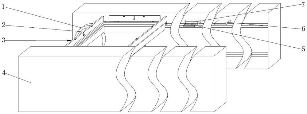
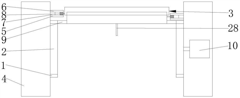
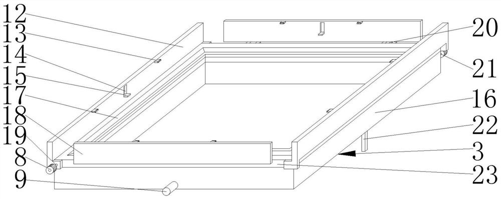
[0028] Such as Figure 1-8As shown, the present invention provides a technical solution: a fixing device for the production of computer motherboards, including two fixing plates 4, the opposite sides of the two fixing plates 4 are rotatably connected with a plurality of turntables 2, and the outer sides of the turntables 2 A rotating belt 1 is sleeved, and a fixing device 3 is arranged between the two fixing plates 4. The fixing device 3 includes a lower fixing f


PUM


Abstract

The invention relates to the technical field of fixing equipment, and discloses a fixing device for computer mainboard production. The fixing device comprises two fixing plates, the opposite sides of the two fixing plates are rotatably connected with a plurality of turntables, and the outer sides of the turntables are sleeved with rotating belts. By arranging a lower fixing frame, a fourth rotating rod, a fourth gear, a third tooth groove and a supporting rod, in this way, when the lower fixing frame moves, the angle of a mainboard needs to be adjusted, a first gear on the rear portion passes through an upper toothed plate on the rear portion, the first gear drives the fourth rotating rod to rotate, the fourth rotating rod drives the fourth gear to rotate in the third tooth groove, and therefore the supporting rod is driven to move upwards, the angle of an upper fixing frame is adjusted, after the procedure is completed, when the rear first gear passes through a rear lower toothed plate, a convex block is pressed into a movable hole by a top block, a pull rope is pressed by the convex block, a clamping block is retracted into a storage groove, then the first gear is in contact with the lower toothed plate, and the first gear drives the fourth rotating rod to rotate to lower the upper fixing frame.

Description


Claims


Application Information

Patent Timeline
Owner NANJING VOCATIONAL UNIV OF IND TECH
Why Eureka
Try Eureka