Self-shearing packaging decoration printing machine

A printing machine and self-shearing technology, which is applied to printing machines, rotary printing machines, printing, etc., can solve the problems of different tightness, affecting printing quality, and shaking of substrates, so as to improve printing quality, protect normal operation, Avoid the effect of slipping

Inactive Publication Date: 2021-09-17
安徽省三环康乐包装材料有限公司
View PDF7 Cites 0 Cited by
  • Summary
  • Abstract
  • Description
  • Claims
  • Application Information

AI Technical Summary

Benefits of technology

This patented technology describes an improved method for packaging products with a special type of film called Self-Cut Film (SCM). These packages are designed to prevent damage from external factors such as impact or pressure during transportation without losing their effectiveness due to insufficient tensile forces applied thereto. Additionally, these packages have specific dimensions depending upon how tightly they fit together. By applying stress at different points along certain directions within this space, the films become stronger overall, ensuring better protection against shock loads. Overall, this process helps improve productivity and reduce costs associated therewith.

Problems solved by technology

This patented describes how printer machines are designed with features like wrapping or labelled packages on their surfaces. However, due to variations in thickness caused by changes overtime from production to use, these differences can cause issues such as sticking between layers within the package's structure, leading to poorly printed characters or labels being stuck together. Additionally, current methods require manual intervention at regular intervals, reducing overall printing speed while increasing costs associated with maintenance tasks. Therefore, this technology proposes a solution where the printing mechanism itself helps keep track of its position relative to the base material without requiring any extra effort.

Method used


Image

  • Self-shearing packaging decoration printing machine
  • Self-shearing packaging decoration printing machine
  • Self-shearing packaging decoration printing machine

Examples


Embodiment 1

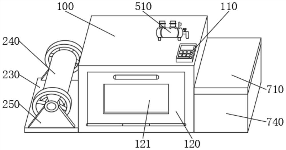
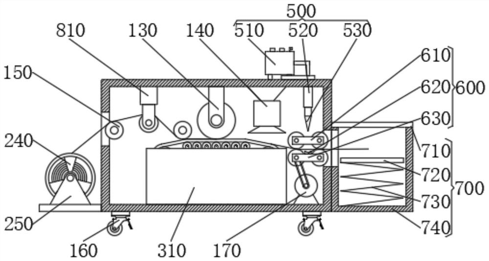
[0026] see Figure 1-3 and Figure 5-6, the present invention provides a technical solution: a drying device for textiles, including a main body 100, an unwinding mechanism 200, a supporting mechanism 300, a transmission mechanism 400, a shearing mechanism 500, a fixing mechanism 600, a collecting mechanism 700 and a tensioning mechanism 800, the unwinding mechanism 200 is fixedly connected to the lower side of the left side wall of the main body 100, the support mechanism 300 is fixedly connected to the middle of the inner cavity bottom of the main body 100, the transmission mechanism 400 is rotatably connected to the inner cavity of the supporting mechanism 300, and the shearing mechanism 500 runs through Fixedly connected to the top right side of the body 100, the fixing mechanism 600 is rotatably connected to the middle of the right side of the rear side wall of the body 100, the collection mechanism 700 is fixedly connected to the lower side of the right side wall of the bod

Embodiment 2

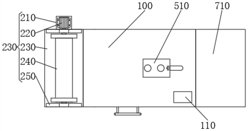
[0028] see figure 1 and Figure 3-4 , the present invention provides a technical solution: a drying device for textiles, including a main body 100, an unwinding mechanism 200, a supporting mechanism 300, a transmission mechanism 400, a shearing mechanism 500, a fixing mechanism 600, a collecting mechanism 700 and a tensioning mechanism 800, the unwinding mechanism 200 is fixedly connected to the lower side of the left side wall of the main body 100, the support mechanism 300 is fixedly connected to the middle of the inner cavity bottom of the main body 100, the transmission mechanism 400 is rotatably connected to the inner cavity of the supporting mechanism 300, and the shearing mechanism 500 runs through Fixedly connected to the top right side of the body 100, the fixing mechanism 600 is rotatably connected to the middle of the right side of the rear side wall of the body 100, the collection mechanism 700 is fixedly connected to the lower side of the right side wall of the body

Embodiment 3

[0030] see Figure 1-3 and Figure 5 , the present invention provides a technical solution: a drying device for textiles, including a main body 100, an unwinding mechanism 200, a supporting mechanism 300, a transmission mechanism 400, a shearing mechanism 500, a fixing mechanism 600, a collecting mechanism 700 and a tensioning mechanism 800, the unwinding mechanism 200 is fixedly connected to the lower side of the left side wall of the main body 100, the support mechanism 300 is fixedly connected to the middle of the inner cavity bottom of the main body 100, the transmission mechanism 400 is rotatably connected to the inner cavity of the supporting mechanism 300, and the shearing mechanism 500 runs through Fixedly connected to the top right side of the body 100, the fixing mechanism 600 is rotatably connected to the middle of the right side of the rear side wall of the body 100, the collection mechanism 700 is fixedly connected to the lower side of the right side wall of the body


PUM


Abstract

The invention discloses a self-shearing packaging decoration printing machine in the technical field of printing machines. The self-shearing packaging decoration printing machine comprises a body, an unwinding mechanism, a supporting mechanism, a transmission mechanism, a shearing mechanism, a fixing mechanism, a collecting mechanism and a tensioning mechanism, wherein the unwinding mechanism is fixed connected to the lower side of the left side wall of the body; the supporting mechanism is fixedly connected to the middle of the bottom of an inner cavity of the body; the transmission mechanism is rotationally connected to an inner cavity of the supporting mechanism; the shearing mechanism is fixedly connected to the right side of the top of the body in a penetrating mode; the fixing mechanism is rotationally connected to the middle of the right side of the rear side wall of the inner cavity of the body; the collecting mechanism is fixedly connected to the lower side of the right side wall of the body; and the tensioning mechanism is fixedly connected to the left side of the top of an inner cavity of the body. The self-shearing packaging decoration printing machine is reasonable in structural design, and capable of protecting the normal operation of the equipment, improving the printing quality and the printing working efficiency and meanwhile reducing the working intensity of workers.

Description


Claims


Application Information

Patent Timeline
Owner 安徽省三环康乐包装材料有限公司
Why Eureka
Try Eureka