Offshore wind power negative pressure barrel base hydraulic device and control method

A hydraulic device, offshore wind power technology, applied in wind power generation, monitoring of wind turbines, and configuration of installation/support of wind turbines, etc. Automatic positioning, easy to use and labor-saving effect

Pending Publication Date: 2021-11-05
伊克森(厦门)液压科技有限公司
View PDF0 Cites 0 Cited by
  • Summary
  • Abstract
  • Description
  • Claims
  • Application Information

AI Technical Summary

Benefits of technology

This new design allows for accurate and automated adjustment of an underwater sink by controllably moving it along its length while being locked tightly onto a tube or pipeline. It also includes a special feature where there are two parts - one part called the hydrous unit (HU) attached to the tank's support cylinders and another part called an electric magnet assembly used to hold down the HU when no power supply comes through them. These technical improvements make this system more efficient than previous designs but still work well even if they were manually operated.

Problems solved by technology

Technological Problem: Current offshore hydroelectric installations are limited due to factors such as poor location accuracy during drilling operations or lack of automation capabilities when installing them without human intervention. There has been some attempts at improving these issues but they still require significant effort and skill level compared to other methods like self-installation techniques.

Method used


Image

  • Offshore wind power negative pressure barrel base hydraulic device and control method
  • Offshore wind power negative pressure barrel base hydraulic device and control method
  • Offshore wind power negative pressure barrel base hydraulic device and control method

Examples


Embodiment 1

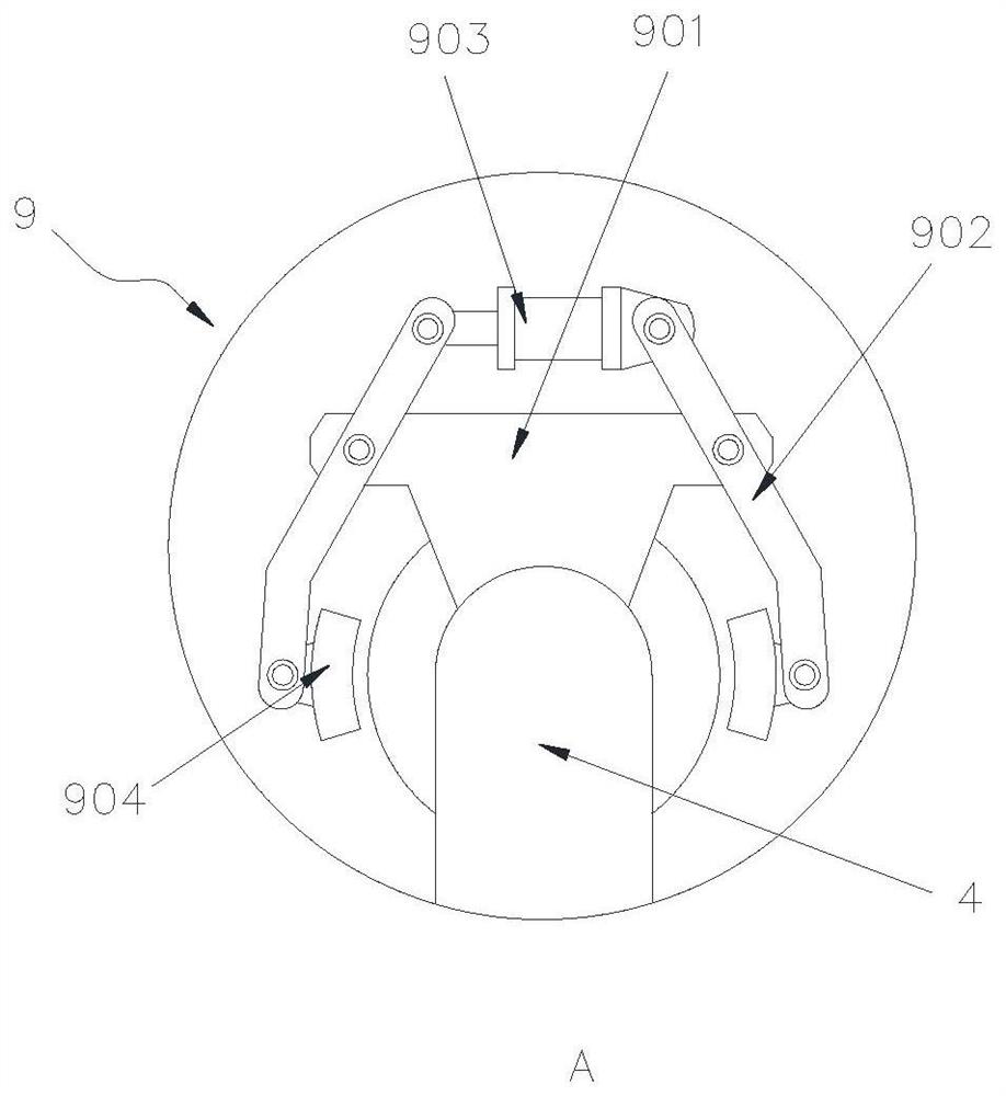
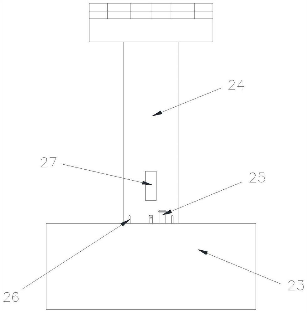
[0040] refer to figure 1 with figure 2 , an offshore wind power negative pressure barrel base hydraulic device, including a frame 1, a bidirectional suction pump 2, a suction pipe 3, a delivery pipe 4 and a discharge pipe 5 are mounted on the frame 1. Wherein, one end of the suction pipe 3 is connected with one end of the suction pump 2, and the other end of the suction pipe 3 is used to communicate with the sea water outside the negative pressure barrel; one end of the delivery pipe 4 is connected with the other end of the suction pump 2, The other end of delivery pipe 4 is used to be connected with the docking pipe 25 on the negative pressure barrel; one end of discharge pipe 5 communicates with the middle section of delivery pipe 4, and the other end of discharge pipe 5 is used for discharging the seawater in the negative pressure barrel.

[0041] A first control valve 6 is installed on the discharge pipe 5 , and the first control valve 6 is used to control the on-off of the

Embodiment 2

[0068] A method for controlling the hydraulic device of an offshore wind power negative pressure barrel base, specifically, when sinking into the base:

[0069] S1. Lock the hydraulic device and the negative pressure barrel together through the automatic locking mechanism, and complete the docking of the delivery pipe of the hydraulic device and the docking pipe of the negative pressure barrel, and connect the hydraulic device with the control equipment on the ship through cables;

[0070] S2. Open the first control valve and close the second control valve, lift the negative pressure barrel into the air and lower it slowly by the lifting equipment on the construction ship, so that the negative pressure barrel slowly sinks into the seabed. When the negative pressure barrel reaches the seabed, the bottom of the negative pressure barrel Buckle the seabed, so that the inside of the negative pressure barrel forms a sealed space, and then the negative pressure barrel sinks to a certain


PUM


Abstract

The invention discloses an offshore wind power negative pressure barrel base hydraulic device which comprises a rack, a suction pump, a suction pipe, a conveying pipe and a discharge pipe. A clamping mechanism is arranged at the butt joint end of the conveying pipe. The hydraulic device further comprises a locking mechanism, wherein an electromagnet is installed at the front end of the rack; a pair of rotatable supporting arms is arranged on the two sides of the electromagnet; a longitudinal wheel module and a circumferential wheel module are arranged on each supporting arm; an elastic telescopic mechanism is arranged between the rear part of each supporting arm and the front part of the rack; a distance sensor is arranged at the bottom of the rack; and a photoelectric sensor is arranged at the front part of the rack. The device further comprises a controller. According to the hydraulic device, the electromagnet is matched with the longitudinal wheel modules and the circumferential wheel modules, so that the device can be attracted to a supporting barrel of a negative pressure barrel, vertical movement and circumferential movement around the supporting barrel of the hydraulic device are accurately controlled, automatic sinking, automatic positioning and automatic butt-joint locking of the hydraulic device are achieved, and the hydraulic device is simple and labor-saving. The hydraulic device can be used 100 meters deep underwater without leakage.

Description


Claims


Application Information

Patent Timeline
Owner 伊克森(厦门)液压科技有限公司
Why Eureka
Try Eureka