Imaging equipment of automatic detection machine for dry width of frame sealing glue and imaging method thereof

An imaging device and detection machine technology, applied in mechanical equipment, supporting machines, image communication, etc., can solve the problems of reducing the practicability of the device and the picture is not comprehensive enough, so as to achieve the effect of improving practicability and convenience

Pending Publication Date: 2021-12-28
南京嘉龙盛电子科技有限公司
View PDF0 Cites 0 Cited by
  • Summary
  • Abstract
  • Description
  • Claims
  • Application Information

AI Technical Summary

Problems solved by technology

[0003] In the prior art, when designing and manufacturing the imaging equipment of the sealing glue dry width automatic detection machine, most designers will pay attention to the imaging clarity of the design device, so that it can be easier to detect the defect area and colloid when zooming in on the imaging residue, but when using this device for imaging detection for a long time, if the lens structure at the upper end of the device does not have the characteristics of flexible movement, it will affect the angle and position of the device's imaging, making the picture after imaging not comprehensive enough, thereby reducing the practicality of the device sex

Method used


Image

  • Imaging equipment of automatic detection machine for dry width of frame sealing glue and imaging method thereof
  • Imaging equipment of automatic detection machine for dry width of frame sealing glue and imaging method thereof
  • Imaging equipment of automatic detection machine for dry width of frame sealing glue and imaging method thereof

Examples


Example Embodiment

[0024] The technical solutions in the embodiments of the present invention will be clearly and completely described below with reference to the accompanying drawings in the embodiments of the present invention. Obviously, the described embodiments are only a part of the embodiments of the present invention, but not all of the embodiments. Based on the embodiments of the present invention, all other embodiments obtained by those of ordinary skill in the art without creative efforts shall fall within the protection scope of the present invention.

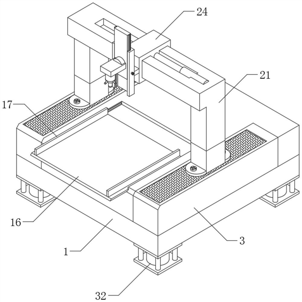
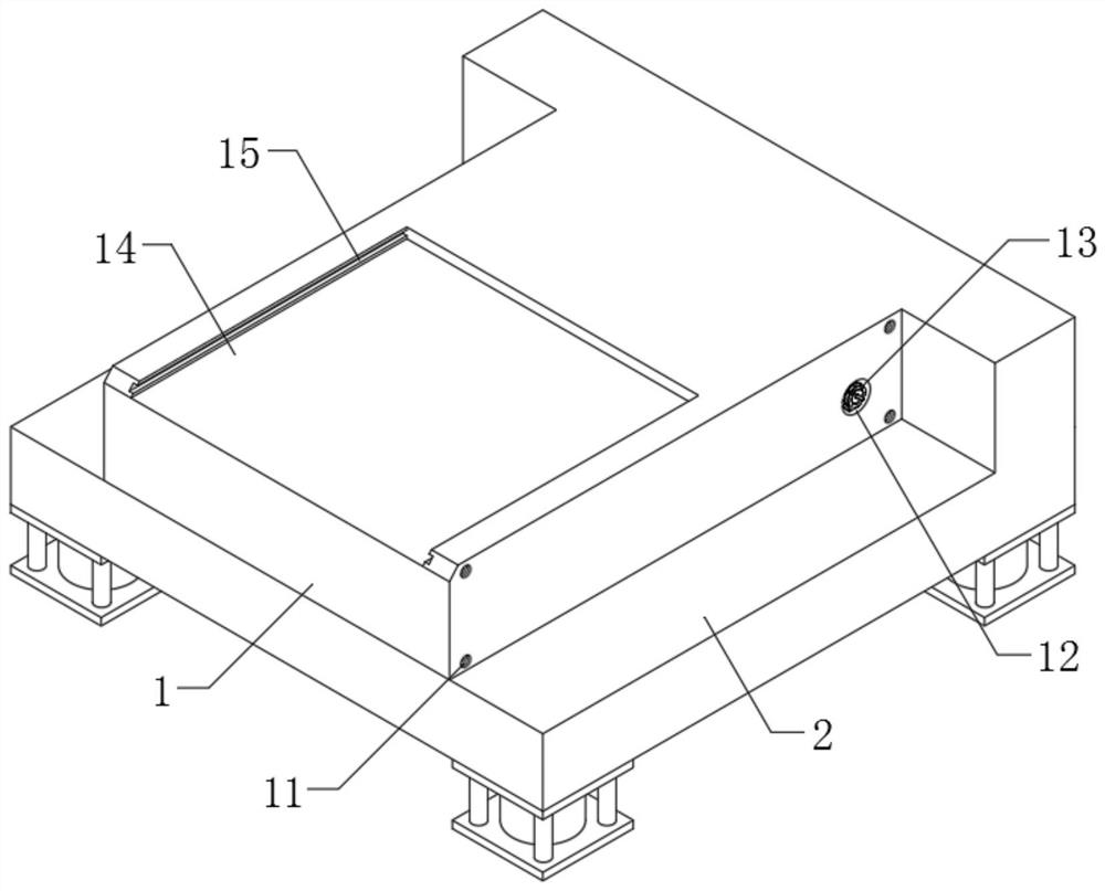
[0025] The present invention provides such as Figure 1-5 An imaging device and an imaging method of an automatic detection machine for the dry width of a frame sealing glue shown, including a support base 1, the inner walls of the two first chutes 15 are fitted with transparent panels 16, and the two ends of the transparent panels 16 are provided with transparent panels 16. The outer walls are respectively slidably connected with the in


PUM


Abstract

The invention discloses imaging equipment of an automatic detection machine for the dry width of frame sealing glue and an imaging method thereof. The imaging equipment comprises a supporting base, first clamping grooves are formed in the edges of the two sides of the top end of the supporting base, protective shells are arranged on the inner walls of the two first clamping grooves in a clamped mode, and through grooves are formed in the middles of the top ends of the two protective shells; the inner walls of the two through grooves communicate with the inner walls of the two protective shells correspondingly, and transmission rollers are rotationally arranged at the two ends of the two sides of the inner walls of the two through grooves correspondingly, wherein conveying belts are arranged on the outer walls of the two transmission rollers in a transmission mode correspondingly. According to the invention, a motor of a mounting groove on one side of a first clamping groove at two ends is started, so that a belt pulley drives four transmission rollers to start to rotate through a linkage belt, and then a transmission belt drives a supporting structure with a lens at the upper end to start to move, scan and image; and full-range lens detection is carried out on the frame sealing screen at the upper end of the supporting base, so the practicability of the device is improved.

Description


Claims


Application Information

Patent Timeline
Owner 南京嘉龙盛电子科技有限公司
Why Eureka
Try Eureka