Fire extinguishing device of oil field heating furnace

A technology of fire extinguishing device and heating furnace, which is applied in the control of fluid heaters, fluid heaters, lighting and heating equipment, etc., can solve problems such as difficulty in extinguishing fire with torches and fires

Pending Publication Date: 2022-01-07
列斯丽(深圳)技术有限公司
View PDF0 Cites 0 Cited by
  • Summary
  • Abstract
  • Description
  • Claims
  • Application Information

AI Technical Summary

Problems solved by technology

However, if the torch is perforated by fire, the multiphase mixture will flow into the torch and cause a fire. At present, there is no fire extinguishi

Method used


Image

  • Fire extinguishing device of oil field heating furnace
  • Fire extinguishing device of oil field heating furnace
  • Fire extinguishing device of oil field heating furnace

Examples


Embodiment Construction

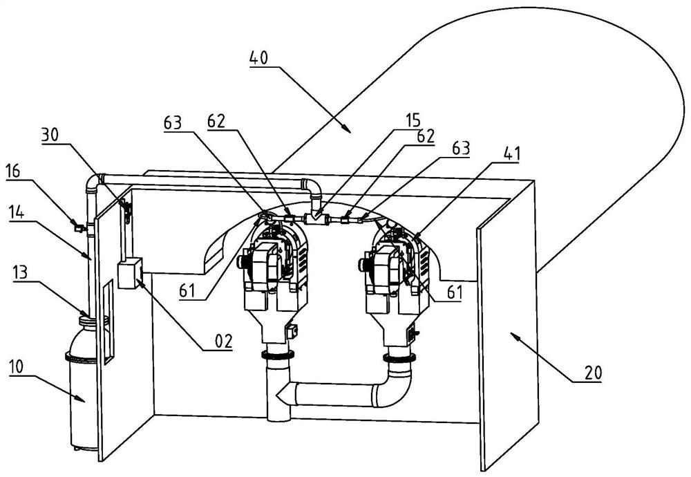
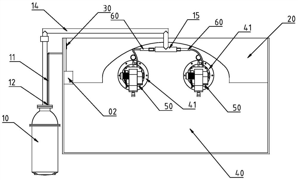
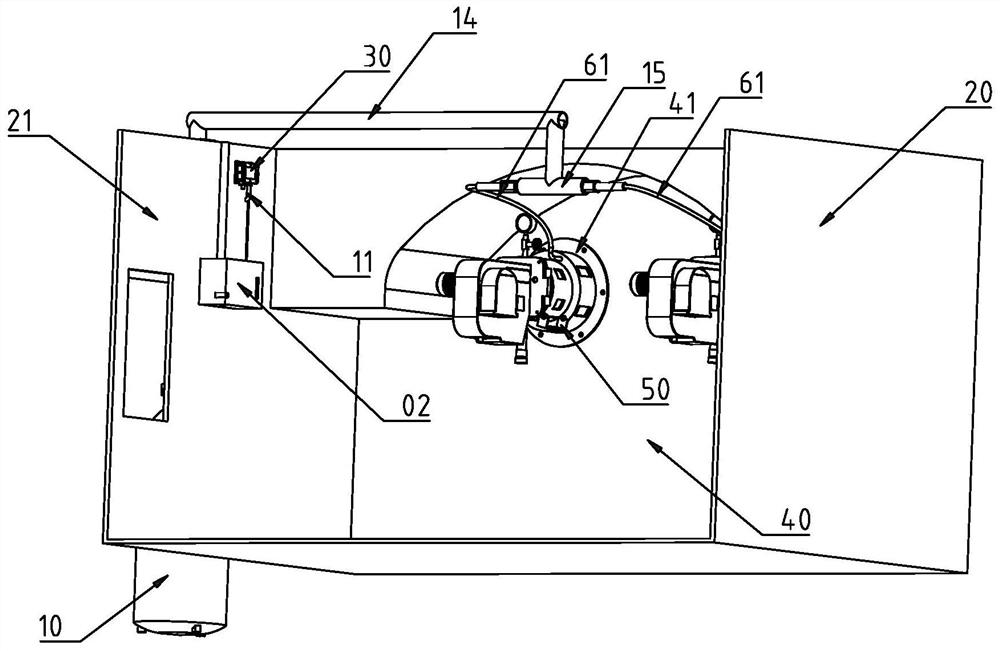
[0027] The structure of the oil field heating furnace fire extinguishing device of the embodiment of the present invention is as follows: Figure 1 to Figure 6 As shown, it includes a smoke generator 10 as a fire extinguisher, a control circuit, a main pipeline 14 for delivering smoke, a three-way joint 15 and two torch fire extinguishing units 60 . The oil field heating furnace 40 generally has two torches, so two torch fire extinguishing units 60 need to be equipped.

[0028] The gas fire extinguishing medium generator can also use trifluoromethane (nitrogen) generator, carbon dioxide generator, heptafluoropropane generator or perfluorohexanone generator, and the gas fire extinguishing medium generator in this embodiment is described by taking smoke generator as an example.

[0029] Each torch fire extinguishing unit 60 includes a branch pipeline 61, an electric control valve 62, a flash pressure sensor 63, a liquid leakage detection sensor 50 and an image video flame recognize


PUM


Abstract

The invention discloses a fire extinguishing device of an oil field heating furnace. The device comprises a gas fire extinguishing medium generator serving as a fire extinguisher, a control circuit, a main pipeline for conveying a gas fire extinguishing medium and a fire tube fire extinguishing unit, the fire tube fire extinguishing unit comprises a branch pipeline and an electric control valve, an inlet of the main pipeline is connected with a gas fire extinguishing medium outlet of the gas fire extinguishing medium generator, an inlet of the branch pipeline is connected with the main pipeline; the electric control valve is in series connection with the branch pipeline, an outlet of the branch pipeline is connected with a fire tube of the oil field heating furnace; and the control circuit comprises a controller, and the control end of the electric control valve is connected with the control signal output end of the controller. Once liquid leakage of the fire tube of the oil field heating furnace is found, the control circuit starts the gas fire extinguishing medium generator, the gas fire extinguishing medium is conveyed into the fire tube through the main pipeline and the branch pipeline, and fire disasters caused by liquid leakage in the fire cylinder can be rapidly extinguished.

Description


Claims


Application Information

Patent Timeline
Owner 列斯丽(深圳)技术有限公司
Why Eureka
Try Eureka