Laser drilling hidden crack testing method for MWT battery

A technology of laser drilling and testing methods, which is applied in optical testing flaws/defects, semiconductor/solid-state device testing/measurement, circuits, etc., which can solve the problems of batch defective products flowing into subsequent processes, and inability to directly judge silicon wafer cracks. , to achieve the effect of preventing the use of hidden dangers

Inactive Publication Date: 2022-01-11
南京日托光伏新能源有限公司
View PDF4 Cites 0 Cited by
  • Summary
  • Abstract
  • Description
  • Claims
  • Application Information

AI Technical Summary

Problems solved by technology

[0002] During the production process of MWT batteries, the laser drilling process is used to drill holes on the surface of the battery. During the laser drilling process, silicon slag is produced and under the action of drilling, it will be impossible to directly judge whether there are cracks in the silicon wafer with the naked eye, especially at the edge of the hole. , if no cracks are found and continued production will lead to batch defective products flowing into the subsequent process

Method used


Image

  • Laser drilling hidden crack testing method for MWT battery
  • Laser drilling hidden crack testing method for MWT battery

Examples


Example Embodiment

[0014] Next, the technical solutions in the embodiments of the present invention will be described in connection with the drawings of the embodiments of the present invention, and it is understood that the described embodiments are merely the embodiments of the present invention, not all of the embodiments. Based on the embodiments of the present invention, those of ordinary skill in the art will belong to the scope of the present invention in the scope of the present invention without making creative labor premises.

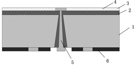
[0015] The MWT battery prepared by the production of the present invention figure 1 As shown, the front surface of the substrate 1 is provided with the n emitter 2 and the SiNx reduction membrane 3, and the Sinx reduction film 3 is distributed on the bone line 4, and the back surface of the substrate is coated with an aluminum back field 6.

[0016] The present invention employs a laser punching, a back-wiring technique to eliminate the main gate line of the front elec


PUM


Abstract

The invention provides a laser drilling hidden crack testing method for an MWT battery, which comprises the steps of eliminating a main grid line of a front electrode on a back contact battery by adopting laser drilling and back wiring technologies, leading current collected by a fine grid line of the front electrode to the back through conductive slurry in a hole, then spraying atomized water to the edge of the hole, and judging whether hidden cracks exist or not by irradiating the punched edge with strong light. After detection, if hidden cracks exist, the finished product is fed into a waste product area, and if the hidden cracks do not exist, the finished product is fed into a qualified product area. According to the invention, waste products with hidden cracks can be effectively detected after laser drilling, and use hidden dangers caused by defective products are prevented.

Description


Claims


Application Information

Patent Timeline
Owner 南京日托光伏新能源有限公司
Why Eureka
Try Eureka