VOCs removal equipment for low-concentration VOCs waste gas treatment technology

A waste gas treatment and low-concentration technology, applied in membrane technology, gas treatment, air quality improvement, etc., can solve problems such as combustion and absorption that cannot be handled normally

Pending Publication Date: 2022-03-01
江苏京颐环保科技有限公司
View PDF0 Cites 0 Cited by
  • Summary
  • Abstract
  • Description
  • Claims
  • Application Information

AI Technical Summary

Benefits of technology

This patented technology allows for efficient cleaning or treatments involving adding special fluids like oxygen (O2) into an engine's fuel system through various types of nozzles that created jets of fluid called flames. These Flames rotate around inside the machine while delivering chemical agents directly onto it. By connecting these components together via separate tubings, this process can be done efficiently without wasting excessive amounts of liquor during maintenance work.

Problems solved by technology

The technical problem addressed in this patented technology relates to improving the process for removing harmful substances from exhaust gas generated through chemical reactions or burning materials containing these substance(es). Current solutions involve combusted absorbents but their use may result in incomplete removal due to high concentrations of certain types of contaminants present at lower levels than usual. Therefore there needs improvement on how effective an abatement system should work effectively without requiring expensive equipment like catalyst systems.

Method used


Image

  • VOCs removal equipment for low-concentration VOCs waste gas treatment technology
  • VOCs removal equipment for low-concentration VOCs waste gas treatment technology
  • VOCs removal equipment for low-concentration VOCs waste gas treatment technology

Examples


Embodiment Construction

[0042] The technical solution in the present invention will be clearly and completely described below in conjunction with the accompanying drawings. The preferred embodiment in the description is only used as an example, and all other embodiments obtained by those skilled in the art without making creative work, All belong to the protection scope of the present invention.

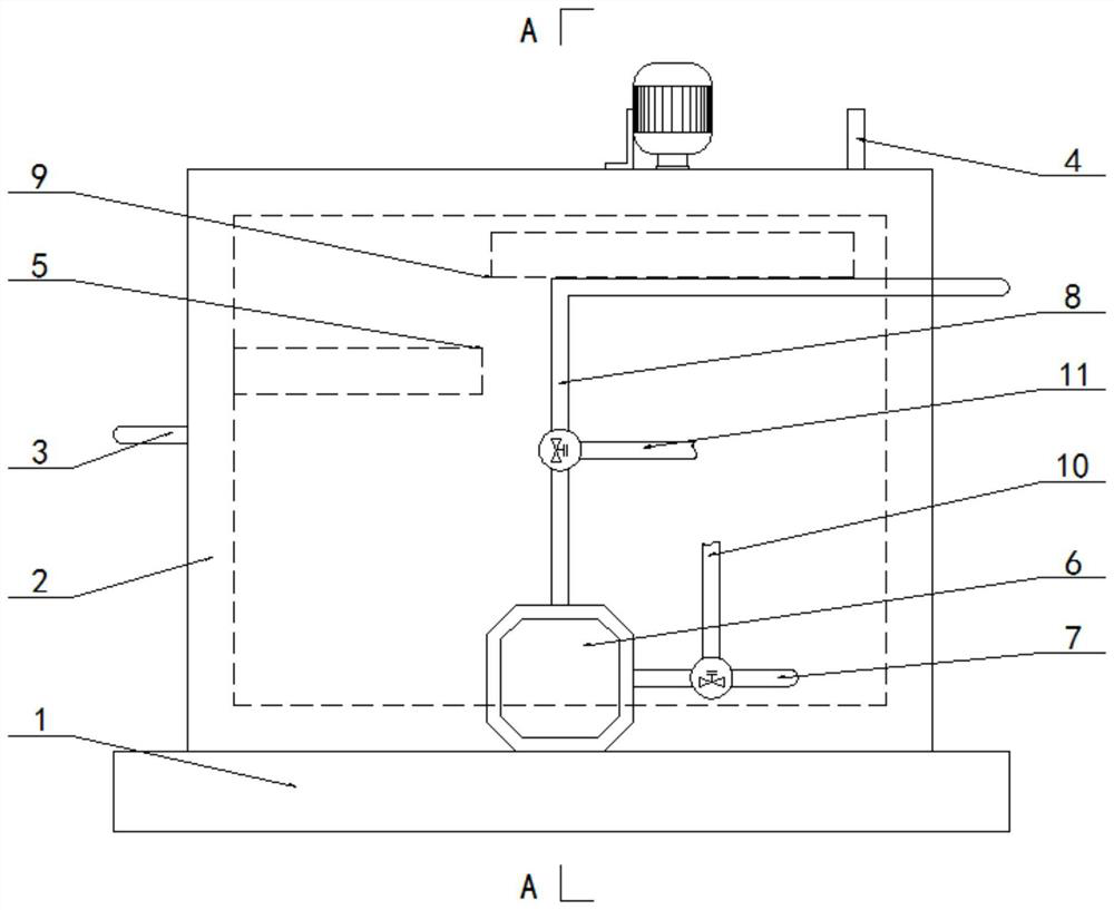
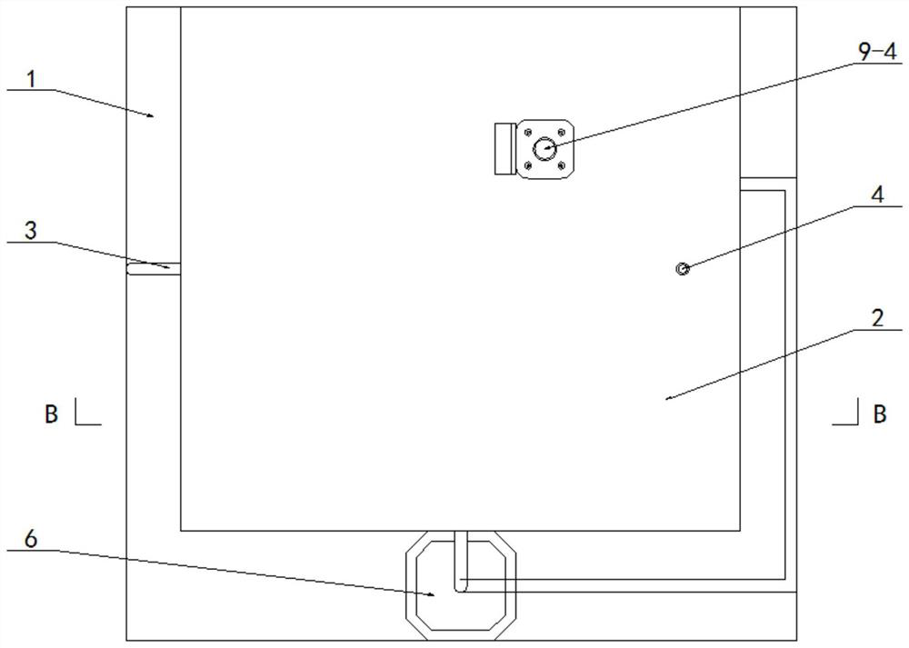
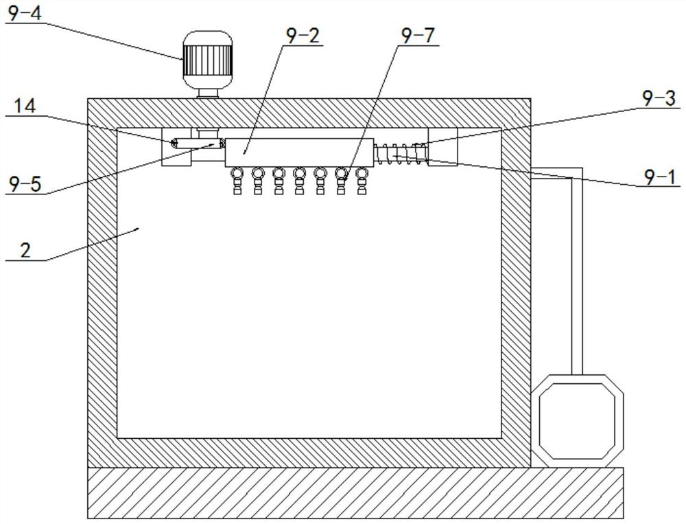
[0043] Such as Figure 1-Figure 5 As shown, this embodiment adopts the following technical solutions:

[0044] It includes a base 1 and a treatment box 2, wherein the treatment box 2 is riveted on the base 1, the left side wall of the treatment box 2 is pierced and fixed with an air inlet pipe 3, and the right side wall of the treatment box 2 is pierced and fixed with an air outlet pipe 4; it also contains:

[0045] Air injection part 5, said air injection part 5 is riveted on the lower inner side wall of processing box 2, and its inlet end is arranged in series with air intake pipe 3;

[0046] A pressurize


PUM


Abstract

The invention discloses VOCs removal equipment for a low-concentration VOCs waste gas treatment technology, and relates to a volatile organic compound waste gas treatment device, a gas spraying piece is fixedly arranged on the lower inner side wall of a treatment box, a pressurizing water pump is fixedly arranged on a base, a water pumping pipe is fixed to the lower end of the front side wall of the treatment box in a penetrating manner, and a spraying pipe is fixed to the upper side wall of the treatment box in a penetrating manner; the spraying piece is fixedly arranged on the upper inner side wall of the treatment box, the water inlet pipe is arranged on the water pumping pipe through a shunt valve, and the water outlet pipe is arranged on the spraying pipe through a shunt valve; according to the waste gas treatment device, the gas inlet structure is arranged, the gas inlet structure is arranged to be a rotatable structure, then when waste gas is introduced for treatment, the waste gas is conveniently and thoroughly mixed with a solution, in addition, the spraying structure is further arranged, the solution for absorption is conveniently and circularly sprayed, the contact area of the solution and the waste gas is increased, and the waste gas dissolving effect is improved.

Description


Claims


Application Information

Patent Timeline
Owner 江苏京颐环保科技有限公司
Why Eureka
Try Eureka