Inner hole cladding laser head

A laser head and cladding technology, applied in metal material coating process, coating and other directions, can solve the problems of uneven energy distribution of circular spot, uneven repair, etc., to improve repair effect, improve service life, and uniform energy distribution Effect

Inactive Publication Date: 2022-03-01
GANGCHUN LASER TECH (JIANGSU) CO LTD
View PDF0 Cites 1 Cited by
  • Summary
  • Abstract
  • Description
  • Claims
  • Application Information

AI Technical Summary

Benefits of technology

This patented technology uses an internal cavity lining (IL) gun with two different types of optical components: one for directing the lasers towards the workpiece while another helps create evenly distributed radiation patterns without any unevenness over its entire area during processing. Additionally, this design prevents damage caused by contamination particles such as metal shavings or other debris generated when machined parts are being worked upon. Overall, these technical improvements improve the performance and lifespan of the IL guns used for industrial processes like cutting steel plates.

Problems solved by technology

This patented technical problem addressed in this patents relates to improving the accuracy and efficiency during laser welding processes when applying interior plating (IMP) techniques onto metal surfaces that are difficult to access due to their internal structure.

Method used


Image

  • Inner hole cladding laser head
  • Inner hole cladding laser head
  • Inner hole cladding laser head

Examples


Embodiment 1

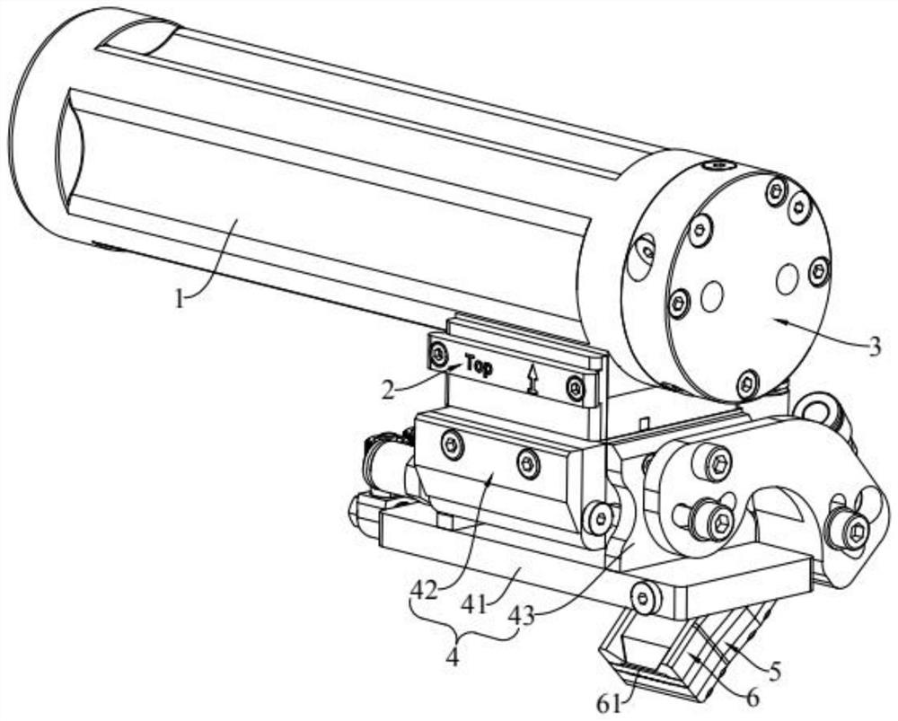
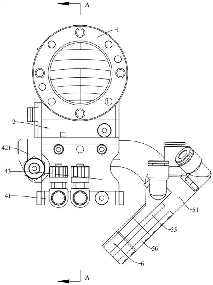
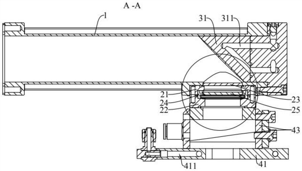
[0048] This embodiment provides a laser head for inner hole cladding, such as Figure 1 to Figure 4 As shown, the inner hole cladding laser head includes a light pipe 1, a protective mirror assembly 2, a reflector assembly 3 arranged at one end of the light pipe 1, a first protection assembly 4, a powder feeding nozzle assembly 5 and a second protection assembly 6 . The protective mirror assembly 2 is arranged on one side of the light pipe 1 at a position corresponding to the mirror assembly 3 , and the reflective mirror assembly 3 can reflect the laser beam in the light pipe 1 to the protective mirror assembly 2 . The mirror assembly 3 can reflect the laser beam into a striped light spot. The first protective assembly 4 is disposed below the protective mirror assembly 2 . The powder feeding nozzle assembly 5 is arranged on one side of the protective mirror assembly 2, and the discharge port of the powder feeding nozzle assembly 5 faces below the first protective assembly 4, an

Embodiment 2

[0059] This embodiment provides a laser head for inner hole cladding. The working principle of this embodiment is the same as that of Embodiment 1, and the similarities will not be repeated here. The difference lies in:

[0060] like Figure 7 As shown, the first guard assembly 4 includes a guard plate 41 and an air knife structure 42 . The protective plate 41 is disposed under the protective mirror assembly 2 through the connecting seat 44 , and the laser beam can pass through the connecting seat 44 and the protective plate 41 in sequence. The air knife structure 42 is arranged under the protective plate 41 , and the air knife structure 42 can blow out an air flow perpendicular to the laser beam emitting direction. In detail, the air knife structure 42 includes an air knife seat 421. There is a cavity in the air knife seat 421. A second air outlet is opened on one side of the air knife seat 421. Gas is introduced into the cavity, and the gas is sprayed from the second air outle


PUM


Abstract

The invention discloses an inner hole cladding laser head, and belongs to the technical field of laser processing. The inner hole cladding laser head comprises a light passing pipe, a protective mirror assembly, a reflecting mirror assembly arranged at one end of the light passing pipe, a first protective assembly, a powder feeding nozzle assembly and a second protective assembly. The protective mirror assembly is arranged at the position, corresponding to the reflecting mirror assembly, of one side of the light passing pipe, and the reflecting mirror assembly reflects the laser beam in the light passing pipe to the protective mirror assembly. The reflector assembly reflects the laser beam into a strip-shaped light spot. The first protection assembly is arranged below the protection glass assembly. The powder feeding nozzle assembly is arranged on one side of the protective glass assembly, a discharging opening of the powder feeding nozzle assembly faces the lower portion of the first protective assembly, and the powder feeding nozzle assembly can spray out the cladding material in a long-strip shape. The second protection assembly is arranged on the powder feeding nozzle assembly and provided with a first air outlet, and the first air outlet is formed above the discharging port. According to the method, cladding can be smoother, the repairing effect is improved, and the service life is prolonged.

Description


Claims


Application Information

Patent Timeline
Owner GANGCHUN LASER TECH (JIANGSU) CO LTD
Why Eureka
Try Eureka