Novel internal circulation engine

An engine and internal circulation technology, applied in mechanical equipment, fluid pressure actuation devices, fluid pressure actuation system components, etc., can solve the problems of inapplicability, high cost, environmental pollution, etc., to reduce the use of resources, practicability high effect

Inactive Publication Date: 2022-03-15
艾士成
View PDF0 Cites 0 Cited by
  • Summary
  • Abstract
  • Description
  • Claims
  • Application Information

AI Technical Summary

Benefits of technology

This new type of engine uses multiple engines with evenly spaced apart cylindrical rotors inside it instead of just one large number of small ones all at once. An external fluid supply makes sure there's enough lubricant for each part of these engines without wasting any more than necessary energy or causing damage from excessive pressure on other parts. Overall, this technology improves efficiency while reducing resource usage and ensuring high performance levels over time

Problems solved by technology

The technical problem addressed by this patented technology relates to environmental issues caused by current thermal engine systems such as airplanes, which require fossil fuel for operation. These vehicles also have limitations with regards their ability to emit harmful chemicals into our atmosphere due to factors like weather conditions and limited resources available at certain locations around us.

Method used


Image

  • Novel internal circulation engine
  • Novel internal circulation engine
  • Novel internal circulation engine

Examples


Embodiment Construction

[0020] In order to make the purpose, technical solutions and advantages of the embodiments of the present invention clearer, the technical solutions in the embodiments of the present invention will be clearly and completely described below in conjunction with the drawings in the embodiments of the present invention. Obviously, the described embodiments It is a part of embodiments of the present invention, but not all embodiments. The components of the embodiments of the invention generally described and illustrated in the figures herein may be arranged and designed in a variety of different configurations.

[0021] Accordingly, the following detailed description of the embodiments of the invention provided in the accompanying drawings is not intended to limit the scope of the claimed invention, but merely represents selected embodiments of the invention. Based on the embodiments of the present invention, all other embodiments obtained by persons of ordinary skill in the art witho


PUM


Abstract

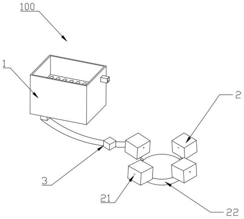
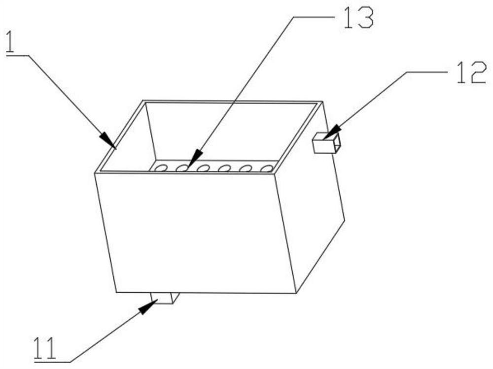
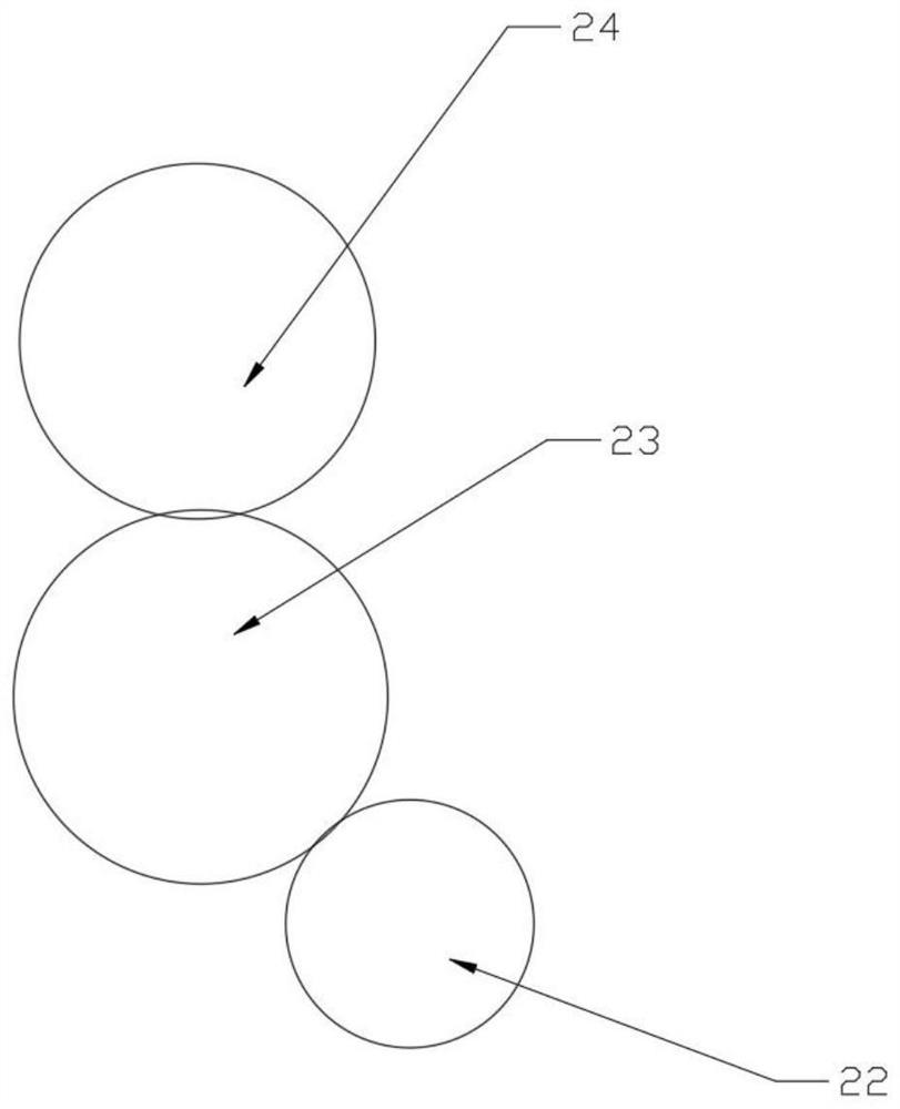
The novel internal circulation engine comprises an oil tank and a main body part connected with the oil tank, the oil tank comprises an oil pump pipe and an oil return pipe, the main body part comprises a plurality of air cylinders, a crankshaft, middle teeth and a cam shaft, the air cylinders are annularly and evenly distributed on the periphery of the crankshaft, and each air cylinder comprises an inlet accelerator, an exhaust accelerator and a piston. Oil enters the main body part through an inlet accelerator of one of the multiple air cylinders, the cam shaft and the crankshaft are driven to rotate through hydraulic pressure, the oil sequentially enters the inlet accelerators of all the air cylinders, the oil enters the oil return pipe through an exhaust accelerator, and after the oil enters one of the multiple air cylinders through an oil tank, the oil enters the oil return pipe through the exhaust accelerator. According to the technical scheme, the crankshaft connected with the oil tank is hydraulically driven, so that the crankshaft and the cam shaft in transmission connection with the crankshaft are driven to rotate, oil in the oil tank enters the air cylinder through the oil pump pipe to push the piston, step-by-step internal circulation power driving of the engine is achieved, resource use is effectively reduced through the design of the scheme, and practicability is high.

Description


Claims


Application Information

Patent Timeline
Owner 艾士成
Why Eureka
Try Eureka